Understanding R-Values and K-Factors in Considering Thermal Resistance

Described in their most basic terms, R-value is a measure of heat resistance, while U-factor (also know as U-value) is a measure of heat transfer (heat gain or loss). The lesser known K-factor is simply the reciprocal of the R-value of the insulation divided by the thickness. What they all have in common is a relationship to the effectiveness of insulation material in resisting heat flow through a roof or wall element. There are different ways that this would be spec’d from a manufacturer to an architect or engineer. While the terminology might be familiar, the specifics are not always as clear cut as they seem. Understanding the differences will allow architects to make smart and effective choices to suit a given project’s needs.

Let’s consider some of the variables that might have an impact on what to look for and which metric to spec. As means of illustration, put yourself in the shows of a fiberglass or insulation supplier. You have a product, you know what it’s rated to, you know what the performance capability is, it’s been spec’d out to you—and you submit the bid based on those factors. But at that point you inevitably lose control over how the specs would actually get implemented. For instance, the architect may take that spec and incorporate it into a wall where it’s not used the most efficient way. This may not even be the result of a mistake; it could just be that other project elements have taken over.

Factor
Choosing the right insulation for the project can provide the building significant energy savings.

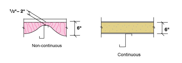
A good example would be stud walls. The fiberglass insulation supplier might indicate a given R-value, such as R-19. This would be the heat resistance value. The architect might spec and submit that bid to supply x number of square feet of that insulation based on that R-value. However, it could be cut or delivered in rolls and designed to fit between the metal studs. Metal studs are much more conductive than insulation and they provide an alternate path for the heat to flow through the assembly, almost irrespective of what the R-value and insulation is. Given these factors, the architect might have to make tradeoffs.

Choosing U-Factor

Because of all the variables encountered with R-value, U-factor is actually more recommended and reliable, and it more appropriately meets code requirements.* The concept of U-factor relates to the heat transfer coefficient but is described in the code as total heat flow per unit area through the assembly inclusive of all the short circuits as it is planned out to be built. So, an architect or engineer would know the stud spacing, the cladding material, the interior finish material and the R-value of the insulation. With that information in hand, one can go to a textbook, ASHRAE 90.1 or the ASHRAE Book of Fundamentals and find the U-factor for the assembly. It is this U-factor that is actually compared against the code requirements. It’s a better way to spec because it already takes into consideration all those things that come into play and encourages the use of suppliers (such as MBCI) that staff people who can help do those calculations or give assistance as opposed to saying, “I need R-19” and then wind up with a building that’s bridged or has more short circuits than anticipated—and having the building not perform as needed. This, in essence, is the key difference between R-value and U-factor.

A Word About K-Factor

As for K-factor, as noted this is the thickness of the insulation divided by the R-value. Its intention is to spec out an insulation when you’re not entirely sure what thickness it will be at the time you spec it out. This is fine for design-build scenarios but not a good practice for a hard bid. Bottom line: U-factor is most often the most reliable choice.

*Note: The code defines U-factor as discussed but underlying heat transfer theory may describe U-factor as 1/R-value. Insualtion suppliers might invert it and make it an R-value (but doesn’t take all the variables into consideration). Therefore, an architect would be advised to specify a “U-factor in compliance with ASHRAE, ” which includes thermal bridges, joints, etc.

The Case for Day One Weathertightness Warranties

Once upon a time, a “standard warranty” was indeed the industry standard for weather tightness warranties in the metal roofing realm. To make a long story short, this meant that manufacturers supplied a “manufacturer’s standard warranty” based on an initial review of the details to ensure that the roof could be properly installed but left it up to others to ensure that the details were followed. If the roof was not properly installed and resulted in a leak then the manufacturer’s warranty did not cover it. At this point, the project had been closed out and the installer was long gone, sometimes even out of business. The owner, architect, general contractor, installer and manufacturer were then at odds with each other leading to dissatisfaction and frustration all around.

Warranty Evolution

In the mid ’90s, the Single Source or Day One warranty was born and quickly caught on throughout the metal roofing industry. Generally, this warranty required that the roofing contractor come to the manufacturer’s training course to be trained in the proper installation of their roof system(s). In addition, the manufacturer typically required inspections at the beginning, middle of the roof installation with a final inspection just before the crew demobilized from the project. Once the warranty was issued, the manufacturer was responsible to the building owner from the date of substantial completion for the weathertightness of the roof. To be sure, there are still terms and conditions to the warranty, just like with any type of product warranty. For instance, the warranties don’t cover leaks caused by natural disasters or damage caused by other trades on the roof. These warranties provide very good coverage and the best part is that the inspections greatly reduce the chance of a leak in the first place, which is what any building owner would want.

Warranties
Chain of Lakes Elementary School featuring Hunter Green SuperLok® Metal Panels

There is an overwhelming agreement on all sides that the evolution toward the Day One warranty has been a good thing for the industry. It has forced installers to do things right from the outset and has compelled manufacturers to come up with good, clear details for some of the more complex architectural elements that architects want to use such as dormers, hips, etc.

Conclusion

Manufacturers all want their roof installations to go smoothly, to look good, be trouble-free and perform as expected for many years. To that end, they are willing to work with specifiers, roofing contractors and others to provide assistance, training and job specific help as needed. To ensure that the roofs are properly installed, the specifiers and contractors need to work together with the manufacturers to ensure good communication about the requirements for the specific project and what each party needs to make the project successful.

What to Know About Dissimilar Metals in Metal Roofing Installations

While metal roofing is often used because of its resiliency, strength and longevity, there are circumstances under which corrosion and other reactions can become real issues, to the great detriment of the system’s performance and life cycle.  Some basic knowledge and awareness of common causes of galvanic corrosion (also called “electrolytic corrosion”) from the use of certain dissimilar metals, can go a long way in mitigating potential problems.

Lead and Copper with Metal Roofing

Metal
Lead from pipe penetrations can deteriorate the metal.

Lead and Copper are the biggest culprits when it comes to shortening the service life of metal roofing due to corrosion.  It almost goes without saying to make sure these metals don’t come into contact with the roof, specifically roofs with Galvalume Plus products.  Here we’ll take a brief look at some of the common problems that can arise.

Due to the high probability of corrosion, it is not advisable to use lead roofing products, such as lead roof jacks for pipe penetrations.

Additionally, graphite, which is the primary material in the common pencil, is extremely corrosive to aluminum and aluminum alloys.  Therefore, it is not advisable to write on a metal panel with a graphite pencil.  In time, the element will eat through the coating and it will rust out.  Eventually, you’ll actually be able to see whatever you wrote on there (that’s not what you want!).  Instead, using a Sharpie or a grease pencil will solve the problem with little to no effort.

Metal Roofing
Chemical damage caused by corrosion and other reactions.

Copper is another metal that does not react well with galvanized metal panels used in many metal roofing systems.  Contact between copper parts and metal roofing can greatly increase the likelihood of corrosion.  Some specifics to keep in mind:

Don’t use treated lumber, which has copper in it.  Sometimes, an installer will set some type of treated lumber post and place something on top of it.

Metal
Copper in condensation can eat through metal, damaging the structure.

Over the course of a year or even a few months, the panel will face deterioration at that spot since once moisture invades it will corrode the panel due to chemical reaction.  A possible solution to avoid this scenario if treated lumber or a lightning system with a cable is needed is to ensure the cable has aluminum instead of copper.

Another situation where copper can be an issue is with an AC unit on the roof.  The AC unit may have copper in the coils, and when condensation drips out on to the roof with copper in the water, those drips onto the metal roof will cause corrosion.  The solution in this case would be to install PVC piping all the way up the roof so the copper does not make contact.

Conclusion

An understanding of these and other potential corrosion pitfalls that exist from using dissimilar metals and knowing the basics behind galvanic reactions will provide a solid basis for the smart, proper selection of roofing installation metals.  With this knowledge in hand, problems can be eliminated before they occur, which in turn can save time, money, and resources, not to mention meeting the all-important goal of extending the life of the metal roof.

Reducing Peak Demand Costs with Cool Metal Roofs

Among the many benefits offered by cool roofs—including a decrease in urban heat island effect or increased roof system longevity—perhaps the most significant is a reduction in peak demand energy usage which directly affects building expenses.

Peak demand is the highest point in the day at which a building draws electrical consumption. A facility’s monthly utility rates are largely determined by the power usage level at this time, so anything that can be done to drive usage down will significantly reduce utility costs. As evidenced by their test values, cool roofs are an effective way to decrease air conditioning loads during peak demand times.

Cool roof values are expressed in terms of solar reflectance and thermal emissivity. The combination of these values is used to determine how hot a surface will become by its ability to reflect solar energy and radiate heat away from itself. Cool roofsare capable of reflecting solar heat away from a building by more than 70 percent. In fact, the U.S. Environmental Protection Agency estimates that ENERGY STAR® qualified roofing products can lower roof surface temperatures by up to 50°F.

According to Jeff Steuben, executive director, and Carolyn Richter, communications manager, Cool Roof Rating Council (CRRC), in a recent Florida Roofing article, “Building occupants can experience improved comfort as compared to a conventional dark roof, as the building’s interior is subject to less thermal flux and stays cooler during warm seasons,” and, “Reduced indoor temperatures lead to energy savings from reduced cooling energy loads.”

Along these lines, contractors can also access a CRRC-provided listing of cool roof rebates, codes and voluntary cool roof programs at: www.coolroofs.org/resources/rebates-and-codes.

Cool Roofing Longevity

In addition to energy efficiency, cool metal roofs are known for extended durability and longevity, with most products offering a 40-year finish warranty.

In fact, a well-noted extensive study, Natural Exposure Testing in California, conducted by the Oak Ridge National Laboratory, found that pre-painted metal roofing maintained higher levels of reflectance, over a three-year period, due to its ability to shed particulate matter, as compared to conventional roofing materials. Further, pre-painted metal roofing has been found to retain 95 percent of its initial solar reflectance over this same three-year period.
Increasing performance and energy savings, solar reflective pigments in cool metal roofs offer higher total solar reflectance and thermal emittance, even in darker colors. With cool roof technology, the ability for the roof to store heat and radiate that heat into the building after sundown is dramatically reduced.

Cool Roofs
Heitmann Residence featuring a Cool Metal Roof

Cool metal roofs are proven to deliver environmental and performance benefits, of which the most significant to building owners is their contribution to the bottom line. Although savings will vary based upon geography, materials and insulation, the U.S. Environmental Protection Agency estimates that reflective roofs can save up to 40 percent of a building’s cooling energy costs.

When utilizing the U.S. Department of Energy’s Cool Roof Peak Calculator, contractors will discover that the total value of energy savings offered by a cool roof averages more than $1,000 annually in most climate zones for a typical commercial building. Furthermore, this applies to both cool roofing installed over both existing roof insulation and new insulation.

Proven Strategy

As established by documented study and significant heat build-up reduction levels, cool roofs are a proven strategy for supporting longer lasting roofs, reducing both utility costs and decreasing a building’s environmental footprint as Steuben and Richter conclude, “cool roofs are one of the most effective ways to obtain energy savings and environmental rewards through building envelope design and re-roofing projects.”

Knowing When to Call the Metal Manufacturer: Part 2

As stated in Part 1 of this series, the success of a metal roof or metal wall project can rest on the installer knowing when something isn’t working or just doesn’t seem right. When that happens, a call to the manufacturer is not just suggested but is really imperative to ensure any potential problem is averted before it’s too late. In addition to the previously discussed scenarios, such as damage to the physical panel or problems with the fasteners, let’s take a closer look at a few other common circumstances under which MBCI recommends immediately reaching out to the manufacturer:

Alignment and Substrate Issues

It is the installer’s responsibility to verify the substrate and check for proper alignment before attaching any sheeting materials. If the installer notices any issues of this sort (either before installation or once they start putting on the sheeting), they should stop and address them immediately. This might include oil canning or other irregularity in the appearance of the panel. The installer should investigate the source. If unable to identify and properly remedy the situation on their own, then a call to the manufacturer’s support team is recommended. They may be able to suggest items to check to help locate the source of the problem—whether it be installation or manufacturing—and from there make suggestions as to the best possible means to address the situation.

Accessories

When physically getting ready to modify a panel system by adding things to the roof (such as snow guards or mechanical curbs) or to walls by installing doors, windows and louvers, these penetrations can have an impact on the system and its weather-tightness and appearance. Oftentimes, other trades—who may or may not have knowledge of the sheeting system—are coming onto the job to perform the accessory installation. It’s wise to visit with manufacturer prior to installation and/or alert the non-metal panel installer of precautions to take when adding accessories.

bad roof jack installation - part #2 ACCESSORIES SECTION
The pipe penetration shown here is not the correct type of piping for metal roofing, and not the correct installation. This can lead to issues with roof performance, including leaking and water damage.

Coordination regarding material types of accessories, fasteners and placement is critical. There are materials that can react negatively with the installed system and lead to damage as well as void manufacturers warranties. Accessories should always be discussed prior to installation. Read more about different types of roof accessories and penetrations in MBCI’s blog article, Roof Penetrations Made By Non-Roofing Contractors.

Panel Engagement

Panel systems have an engineered means by which the panels attach and engage one another as shown in the manufacturer’s installation manuals and project drawings. If at any point the panel will not engage as depicted in the details, installation should be halted and reviewed to determine the cause. This can require a call to the manufacturer to help determine if the matter is site and substrate related or potentially a manufacturing issue.

Do not continue to install the system if the laps are not nesting properly, clips are not engaging as detailed, panel modularity cannot be controlled or if the overall panel is not “resting” on the substrate such that there is excessive bowing and stress in the panel. This is the time to call the manufacturer, as once the material is completely installed, it is much more difficult to determine the cause of a problem and is potentially more expensive to remedy. Additionally, in many cases, full installation constitutes acceptance of the product and the manufacturer’s hands could be tied or extremely limited in being able to assist in remedying after the fact.

By knowing when to be proactive with a call to the manufacturer, installers can mitigate many types of potential pitfalls. And if you’re just not sure, it’s best to call.

For more information on metal roof and wall products and training, MBCI offers courses through its Metal Institute. These courses are available for general training purposes or for those seeking installer certification.

Knowing When to Call the Metal Manufacturer: Part 1

Metal panel installers have a tough job—not only navigating the details of the task at hand but also being confident enough to know when to seek the manufacturer’s guidance. Part of overseeing a successful project is for the installer to know when something is out of his or her comfort zone, beyond their expertise, or just doesn’t look or feel right. And when that’s the case, it’s imperative to call on the manufacturer for input before it’s too late.

Technical support, such as MBCI’s Ask the Technical Expert, can be most useful for answering upfront general product questions. Once the project has started or material is on the jobsite, it’s generally preferable for the installer to go through their sales person or field service/customer service representative rather than sending a question via a website.

When to Seek Assistance from the Manufacturer

First things first: The installer should study the installation manual and construction drawings. If, after that, he or she is experiencing a problem—for instance, the panel doesn’t look right, it’s not engaging properly, it’s not meeting the tolerances stated in the manual, the fasteners that are called out in the drawings are not working or are even missing—then contacting the manufacturer should be the next step. That one simple call can save a lot of time in potential headaches.

Improper Storage of Metal Panels
The above image depicts damage to metal panels caused by improper storage, rendering them unable to install properly.


While it’s not the manufacturer’s direct responsibility to make sure the installer is doing the job on site per the drawing details, a reputable manufacturer can at least provide recommendations when asked how to possibly alleviate or mitigate any number of potential pitfalls, or share common oversights that other installers have made—and how to avoid those same mistakes.

Top Circumstances

Here are two of the top circumstances under which MBCI recommends immediately reaching out to the manufacturer:

  1. Damage to the physical panel itself. If a customer receives materials and there’s suspected or noticeable damage to it, he or she may or may not know what impact that damage could initially have on the system. Notify the manufacturer immediately to assess if it’s a minor issue or if the panels should not be installed because it will be detrimental to the system. No one wants to have to reorder or wait for new materials, but it’s worse to wait until after installation when the impact of removing/replacing is significantly more costly and time-consuming.
  2. Fasteners. Contact the manufacturer if the substrate on site changes in any form from the project details, there is any difficulty with the screws themselves engaging, or any problems with the fastener type. When installing fasteners, make sure to use the ones per the installation details. The manufacturer can assist in verifying the correct fastener is being used in the correct location per the details and per the substrate on site. There could be situations where the installer is not accurately reading the drawing or has substituted an alternative screw not supplied by the manufacturer. Don’t assume. Instead, call.

There are, of course, other scenarios when a call to the manufacturer will save time, money and aggravation for all parties involved in an installation, including alignment and substrate issues, the addition of accessories, and problems with panel engagement. In Part 2 of this topic, we will go into more detail on these additional circumstances.

For more information on metal roof and wall products and training, MBCI offers courses through its Metal Institute. These courses are available for general training purposes or for those seeking installer certification.

Combatting Thermal Bridging with Insulated Metal Panels

When using compressible insulation, say for instance fiberglass batt, consideration must be given to how that insulation is going to be deployed in the actual wall or roof. For instance, installers might place the insulation across the framing members and then smash it down with the cladding and run a screw through to the underlying structure. The problem here is that the insulation is rated with some R-value—and that R-value is determined by an ASTM procedure that also determines what its tested density is. So in essence, it’s ‘fluffy’ insulation.

One manufacturer’s insulation, however, might be thicker than another’s. The contractor is buying an R-value, not a density or a thickness. The insulation is tested to that R-value at whatever thickness and density¹ is needed to achieve it. Let’s say R-19 fiberglass batt is specified, but then it is put in an assembly and smashed down flat… now it’s not R-19 anymore; it’s now R-something else. That’s a thermal bridge—when the insulation’s R-value has been compromised.

Manufacturers have the ability to run long length panels that minimize the number of end joints. This continuity provides significant advantages over traditional insulated materials when designing for energy efficiency. This image illustrates the difference between fiberglass batting made discontinuous by compression between panel and framing members and the continuous insulation provided by insulated metal panels.

Unfortunately, thermal bridging is almost impossible to eliminate. In the example above, another choice might be to put it between studs. Except in this situation, the studs break the insulation. While it’s not pinched, the studs are separating it. Whether the studs are metal or wood, in either case it’s still a significant thermal short circuit or a thermal bridge.

Even with the highest quality insulation systems—insulated metal panels, for example—a joint is required. Building is not possible without putting neighboring panels together. Therefore, insulation is discontinuous. While it’s impossible to avoid thermal bridging, there are two requirements to ensure the building performs the way it needs to perform.

  1. Thermal bridging must be mitigated. In other words, the designer or installer has to try to eliminate as much of it as possible.
  2. If thermal bridging is unavoidable, it must be accounted for in some fashion, which usually means putting more insulation somewhere to make up the difference. This is called a “trade-off” and is allowed by most building energy efficiency codes.²

Why Insulated Metal Panels?

Insulated metal panels then are the best bet, because although the joint is a thermal bridge, in effect, it is not nearly as impactful as breaking a line of fiberglass with a stud or smashing the fiberglass between the panel and a framing member. In the illustration below, R-value doesn’t just vary at that point where the panel and the stud meet. The entire insulation line gets smashed and one would have to go some distance from the stud before the insulation returns to its normal, fluffy thickness. These issues need to be mitigated and accounted for.

assembled side joint
Continuous insulation is critically important to an efficient envelope design. Insulated metal panels, with their side laps designed for concealed fasteners, eliminate the possibility of gaps in the insulation and thermal bridges. Continuous insulation is important because thermal bridges and discontinuities introduced by compressing non-rigid insulations cause the in-place R-Value of the assembly to be less than the tested R-Value of the insulation used. This effect has become a focus in newer energy efficiency codes such as ASHRAE 90.1 and IECC.

Manufacturers such as MBCI and Metl-Span publish insulated metal panels as U-factors because the joint is tested as part of the assembly (both mitigating and accounting for the aforementioned issues). These values can be found on product data sheets and technical bulletins, such as Metl-Span’s Insulation Values technical bulletin, published January 2017.

References

  1. ASTM C 665 – 12, Standard Specification for Mineral-Fiber Blanket Thermal Insulation for Light Frame Construction and Manufactured Housing, Table 1, Footnote c.
  2. ASHRAE 90.1 – 13, Energy Standard for Buildings Except Low-Ride Residential Buildings, Section 5.6
  3. High Performance Green Building Products – INSMP2A (CEU)

Alignment Tolerances of Substrates for Metal Panels

Installers take note! It is your responsibility to ensure the substrate material over which you place the metal panels is in proper alignment before beginning installation. Otherwise, you can suffer some significant negative impacts on the overall appearance of the system.

As we’ve discussed in a previous blog article, Choosing Proper Substrates for Metal Roofing Systems, the substrate (or substructure) rests underneath the metal panels is a key part of the roofing or wall system. It serves two main functions: to act as a base to which the metal material is attached and to serve as a structural member to transfer loads to the primary framing system.

Knowledge is Power

Too many times, inexperienced metal building sheeting installers or sheeting-only contractors may not realize how big an impact alignment can have; it’s very easy to get too far into the process before recognizing there’s a problem. The issues must be dealt with at the very beginning of the process as well as the way through the installation of the panel system, whether it’s roof or wall panel installation, and must be checked frequently.

Major Misconception

One common misconception, especially for those new to the panel system, is that aesthetic anomalies are a result of panel quality. When troubleshooting, the manufacturer will ask a series of questions about the installation and alignment. However, by that stage, the installer may be beyond the point where it’s an easy fix, depending on the circumstances.

Key Considerations

  1. Understand the general panel installation characteristics by reading the installation manual. Become familiar with which screws and clips to use, and how the panels physically connect as well as types of insulation systems that work well with the panel system and if there are any limitations related to insulation types or thicknesses.
  2. Installers must be certain that the substrate material they’re installing over, whether metal or wood or something else, has been properly erected and properly aligned before panel installation begins.
  3. As they’re putting the panels over the substrate, installers should be checking the alignment, whether vertically/horizontally along the leading edge of the panel or inward and outward on the panel itself. With most metal panels, major variances in the substructure will cause the panel to accentuate any errors. As a result, the panels will look unattractive and be difficult to install.
  4. When the panel installation first begins, the installer might not immediately recognize there’s a problem. A variance in the steel or in the substructure can have a big impact, which won’t be known until it’s too late. As an example, consider erecting half a wall on a cloudy day without checking alignment. At the end of the day, it looks fine, but the next day when the sun is shining on it, the “aesthetic delights” due to misalignment are obvious.
  5. Check panels during installation for any damage due to handling, surface irregularities and how it engages or lays on the steel. Do not install any “suspect” panels and contact the manufacturer as needed.

Types of Problems with Alignment

  • Different types of panels can react differently to a substructure out of alignment. Some are more forgiving, and some are terribly unforgiving.
  • Overdriving fasteners combined with improper alignment is a killer 1-2 punch.
  • If alignment is not properly addressed/corrected prior, installers often try to push and pull the panel out of plane, resulting in “oil canning,” a common rippling effect that occurs with improper installation. It should be noted, this often is a direct result of the substrate and/or improper installation and does not have any bearing on performance, weather-tightness and warranty. It doesn’t look nice but is not a cause for rejection.
  • If the steel is out of alignment, the panels can be difficult to engage and perform the way they should.

What Can You Do?

Using a level, laser or a string line, an installer can measure/check the amount that the substructure is either going in or out of plane and correct as needed. For instance, the plane is zero mark-perfectly plumb, perfectly level. There’s an allowable tolerance that the substructure can be out of plane and still be acceptable. Manufacturers often publish recommended tolerances that should always be reviewed. The preferred tolerance being convex (outward) and never concave (inward).

Other Considerations

The main takeaway here is that steps should be taken to prepare a substructure to properly receive the metal panels. Then, diligently check as panels are being installed to ensure proper alignment is maintained and the installer is not inadvertently pushing and pulling them out of alignment, which could result in less than favorable final appearance.

Roof Penetrations Made by Non-roofing Contractors

In our last two posts, we have looked at the proper ways for roofing contractors to address different types of penetrations in metal roofing in order to assure that a watertight seal is achieved from the outset, as well as over the life of the roof. But what happens when another contractor, such as a plumber, electrician, or other trade needs to penetrate the roof? How is the watertightness of the roof assured then?

Warranty Control for a Metal Roof

Most metal roofing warranties are very specific about what is included or not included should a roof leak occur. Therefore, the manufacturer’s warranty should be the first thing that is checked for a particular project to determine whether a seemingly innocent bit of work on the roof has the potential for a loss of warranty coverage. Commonly, qualified roofing contractors need to do the work and it needs to be inspected, but in some cases, supervised work may be acceptable too. Either way, any penetration installed by a trade contractor other than a roofing contractor should be fully coordinated with the architect or owner’s representative, the roofing manufacturer’s representative, the general contractor, and the roofing contractor. Once reviewed, there may be several options on how to proceed.

Guided Installation

For a single or simple penetration, say for a single small mechanical or electrical line, it may be possible to simply work with the trade contractor on the location of the penetration, review in advance that the proper materials are being used, and check the quality of the work for water tightness when complete. (Note: following the guidelines in our prior post on Pipe and Flute Penetrations will provide a good checklist of things to cover.) If everything is appropriately done, then it may be possible to have the roofing manufacturer add the new penetration to the list of items covered under the warranty.

Lightning Rod
Lightning Rod Application for Metal Panels

Coordinated Installation

In some cases, numerous penetrations may be required, such as the installation of multiple lightning rods across a roof. In this case, it might be more prudent to consider a coordinated, cooperative effort to allow each trade to do what it does best and keep the warranty in effect. Instead of an electrician being responsible for the roof penetrations and for lightning rods, let him focus on the lightning protection and wiring aspects of the work. But first, bring in a roofing contractor to advise on the proper locations of the lightning rods and to be the one responsible for the watertight seal. Location advice would include things like avoiding valleys, standing seams, or other areas that are difficult to seal or flash around. The electrician could then make the needed lightning rod penetrations in the agreed-upon locations and complete his work. Following right behind, the roofing contractor could install retrofit rubber roof jacks around the lightning rods and assure that they are sealed properly. Alternatively, the roofing contractor could make the penetration and allow the electrician to install the lightning rod, while the roofing contractor installs an appropriate rubber roof jack over or around it. Either way, the two trades need to  review the process ahead of time and be sure that everyone is on board to produce the best results for everyone involved.

Bottom Line: Think Through Penetrations

roof penetrations
Standing Seam Roof Penetration

Standing seam metal roofs have become more complex in recent years, with more and varied types of roof penetrations. This simply magnifies the need for better communication between the design professional, roof manufacturer, general contractor, roofing contractor, and any of the various trades that might be working on the roof.

When everyone takes the time to plan up front and think through their own needs and the options to get there, everyone wins. The architect/owner representative can ensure that his or her clients get a roof that will perform long-term. The roof manufacturer is able to provide expertise that has been gained over a long period of time through working with similar details on roofs all over the country. The roofing contractor can leave the project knowing that the details are long-term and will mean little chance for leak callbacks. Plus, the general contractor and the building owner can quickly resolve any arguments over which trade is responsible for repairing a roof leak.

Structural Penetrations in Standing Seam Metal Roofs

In our prior post on “Pipe Penetrations in Standing Seam Metal Roofs,” we identified important guidelines for when pipe penetrations are made to metal roofing systems, typically after the metal roofing is installed. That means an opening is cut in the metal roofing, it is properly flashed or sealed, and the penetrating member is passed through it. However, some penetrations are already in place before the roofing contractor shows up. These can be things like vertical members resting on the building structure that support a platform for HVAC equipment above the sloped roof. Or, it can be parapet wall with offsets or other conditions that are already in place. In cases like this, a different approach is needed to assure that the roof remains watertight.

Equipment Platforms for Structural Penetrations

Penetrations
Structural Penetrations in Standing Seam Metal Roofs

From the standpoint of a roofer, a structural equipment platform is a pre-existing condition. The metal roofing industry already recognizes the need to address such situations, particularly on existing buildings, by offering retrofit flashing and curb products. The same, proven approach can be used when pre-existing conditions are encountered on new buildings as well. For example, when structural posts for equipment platforms are encountered running up through the roof plane, roof jacks and curbs specifically designed for retrofit applications should be used. The retrofit roof jack, or boot, should be made out of rubber and be designed to install around the penetration, rather than over it. The boot should ideally rest on a two-piece retrofit pipe curb which can span across one or more standing seams and create a smooth, flat surface for the boot to be attached and sealed. The two-piece design allows for the pipe curb to be properly shingled on the up slope and down slope side of the roofing, thus preventing a “backwater lap,” which will leak. Trying to use only products intended for new construction on such conditions will require unwarranted field modifications or an over-reliance on caulking and sealant, all of which can be prone to problems and failure of the watertight abilities of the roofing.

Parapets

The use of parapet walls around some or all of a perimeter of a building is a common condition. However, if the building shape varies, and the parapet along with it, then there may be some rather uncommon conditions in which the roofing meets an offset or irregularly shaped parapet walls. The issue is that water coming down the sloped roof runs into the offset or other obstruction, causing a buildup of water and a potential leak. The typical approach is to provide a cricket, which is flashed into the parapet wall and diverts water away from the corner created by the offset. It is important, in this case, to be aware that standard sheet metal crickets have not proven to be effective. Instead, welded aluminum crickets and fixtures are recommended to create a truly watertight seal. Also, the welded cricket can be “shingled” into the roof to prevent “backwater laps.” The key is to provide a complete seal at the corners by welding the material, which cannot be done with sheet metal crickets.

Design Planning

The best way to address all of the structural roof penetration issues described here is with proper upfront planning. Avoiding any of these conditions would of course be ideal, and perhaps they can be designed out of some projects. However, if they’re unavoidable, then the roofing contractor and the design professionals need to review the conditions together ahead of time. This advance design planning is the best way to assure that the best, most effective detailing is employed and the proper materials are available on site.

Find a sales representative