Cutting Metal Panels Properly On Site

Cutting metal panels on site is an often-necessary part of installing metal roofing and wall panels. However, using the right tools and methods to ensure the panels remain damage-free is vital. Using the wrong tools can result in rust, rust stains, the voiding of warranties and diminished building service life. In this blog post, we’ll share several common field-cutting techniques and best practices that help ensure good results.


Maintaining Longevity When Cutting Metal Panels On Site

When metal panels are made in a manufacturing facility, the tools and methods used to cut the coated metal coil help protect the cut edge from deterioration like corrosion. When cutting metal panels on a jobsite or in the field, protecting any cut edges is just as important. To understand how to field-cut metal panels without sacrificing the quality and protection delivered from the manufacturing facility, you must first understand the what protects the panels. Most often, metal roof and wall panels are fabricated from Galvalume®-coated steel coil because of its proven longevity. Not only does the Galvalume coating protect the surface area of the metal panels, it has also been shown to be effective along the thin edges of the metal too, as long as those edges are cut properly.

During fabrication, the Galvalume metal panels are cut to length either by shearing while flat before entering the roll former, or by means of a profile shear as the panels exit the roll former. Either method tends to “wipe” the Galvalume coating across the cut edge of the metal panels. This provides superior cut-edge protection from corrosion.

Likewise, when panels arrive on site, any needed field cutting should address the same concerns of protecting the edge of the steel from corrosion. Of course, there are ways of doing the field cutting correctly. However, there are also poor strategies that can lead to real problems. The following are examples of common field cutting tools and the best practices for good results.


Common Tools and Methods for Cutting Metal Panels On Site:

Aviation Snips

Red and green aviation snips are a good choice for small cuts on metal panels, such as around pipe penetrations. These snips will wipe the Galvalume® coating in the same way as factory shears, making them a good choice.

Electric Shears

Electric shears are optimal when making lengthier cuts along the steel, such as cutting a wall panel at a corner or at a door opening. These shears take a ¼” strip of metal out of the panel during the cutting process, which tends to leave both sides of the panel smooth and flat along the cut. Like the aviation snips and factory shears, electric shears will wipe the Galvalume coating and protect the edges.

Mechanical Shears

Mechanical shears are an add-on tool that fit onto a battery-operated impact or screw gun. These shears do not take any metal out of the panel and will leave a slightly wavy edge. Mechanical shears are an excellent choice for bevel cutting standing-seam panels at hips and valleys, since they too wipe the Galvalume coating over the cut edges to offer protection.

Nibblers

A nibbler is a great tool for cutting across corrugations in wall panels to create openings for windows, doors and similar structural additions. A good nibbler typically costs $500-$700 (currently), but is well worth it if you often cut corrugated metal panels. The punch and die in the nibbler tends to wipe the Galvalume across the cut edge as it punches out small, half-moon shaped pieces of panel. However, because these little metal pieces will fall away from the cut, it’s important to contain them so no one walks on them. Otherwise, they can embed in the soles of installer’s shoes and create scratches in roof panels when they walk on the roof.

Skill Saw

Skill saws are an ideal tool for cutting metal panels because of their versatility. This tool can cut either across or parallel to corrugations, whether straight or at an angle. When using a skill saw, it is critical to use a saw blade that cuts cool. Otherwise, the Galvalume coating can melt along the cut edge and become ineffective. In particular, do not use an abrasive blade, which will generate heat and damage the coating.

MBCI Blog: Field Cutting Metal Panels On Site
Panels cut with abrasive blades corrode. A cool-cutting blade leaves a smooth edge.


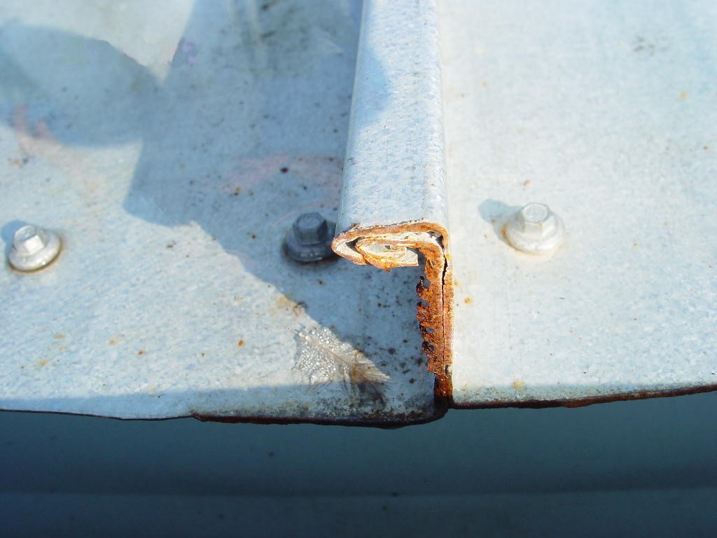
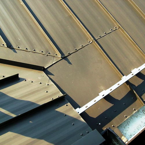
Additionally, its vital to avoid cutting panels on the roof or above other panels. A skill saw blade will throw considerable amounts of steel debris into the air and down onto any panels below. This debris, called swarf, will quickly rust and ultimately cause rust spots in the panels. If enough swarf gathers in one spot, it can rust through the panel.

MBCI Blog: Field-Cutting Metal Panels On Site

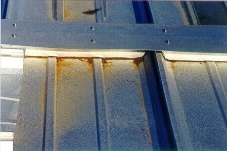
Steel swarf, like this collected at the ridge will rust through the panel.


Which Tools Should To Avoid When Cutting Metal Panels On Site:

Tools that should never be used include:

  • Torches
  • Cut-off saws
  • Reciprocating saws
  • Hacksaws
  • Grinders

All of these tools will melt the Galvalume® coating, causing edge rust just like an abrasive blade would. These tools also throw a lot of steel debris (swarf) onto the panels they cut. This debris will be hot and will embed into the panel coating. This can cause rust spots and bigger problems down the road.

In conclusion, using the right tools and following metal panel manufacturer recommendations when cutting metal on site will help ensure that the panels remain damage-free and the final installation will be a fairly seamless process. Using the wrong tools can result in rust, rust stains, and the voiding of warranties. For more on best practices and recommendations for on-site cutting and installation of metal panels contact your local MBCI representative.

Appropriate Standing Seam Clips for Roof Panels

Part of the beauty and appeal of standing seam metal roofs is that the fasteners holding the metal panels in place are concealed. That gives the roof its clean, continuous appearance that is often desirable, but it also avoids the issue of potential roof leaks around exposed through-fasteners. Concealed fastening doesn’t mean that there aren’t any fasteners, though, it just means they are installed out of sight – underneath the panels. The industry standard approach is to use a metal clip that fits over the edge of a panel and that is secured with a screw type fastener to the structure or substrate below. Then it is covered by an adjacent panel or trim. The important thing to know is that not all panel clips are made the same – for good reasons.

What determines the type of panel clip to use? Here are the most common things to keep in mind:

The Manufacturer

Each manufacturer of metal roofing typically has a range of metal panel types, profiles, and brands that have their own traits and characteristics. As such, they need clips to match and fit with the manufactured panels. Hence, the first place to start with panel clip selection, is for the roofing manufacturer to be clear on the options and choices available that are compatible with their roofing products.

Building Size and Type

Fixed clips (left) and floating clips (right) are two of the most commonly used types of clips.
Fixed clips (left) and floating clips (right) are two commonly used types of clips.

Manufactured metal buildings that include metal roofing commonly use very predictable, coordinated systems. Accordingly, a standard, one piece, “utility clip” is commonly used, primarily for snap together roof panels, on metal buildings that do not exceed certain widths causing undue expansion and contraction. One piece clips allow the roofing panels to expand and contract within the clip profile, but there are limits based on the amount of movement tolerated. Alternatively, in projects where the roofing is attached to something other than a metal building frame or where standing seams are used to secure the panels together, it is advisable to use a two-piece or “floating” clip. In these cases, a base piece is secured to the structure or substrate and the clip fits both into the base and over the roofing panel where it is seamed or folded into the vertical leg of the panel. Using this approach, the clip expands and contracts directly with the metal panel thus moving across the base and keeping the roofing attached.

Insulation

Roof insulation comes in different thicknesses, appropriately so for different climate zones and different roof designs. Since energy codes require at least some of the insulation to fit between the underside of the metal roofing panel and the structure (i.e. above the metal roofing purlins), the metal panel clip needs to be the right height to reach the full height of the insulation up to the top of the roof panel. Hence, manufacturers offer different sizes and heights of panel clips designed to work with different heights of insulation. In many cases, they also recommend the use of a thermal spacer underneath the clip to separate it thermally from the steel structure below. Note that the thermal spacer thickness is dependent on the insulation thickness over the steel purlin only, not the thickness of any insulation under the purlin.

A certified installer should install your standing seam roof to ensure proper installation of clips.

Other Factors

The panel clips connect the roof panels to the roof structure, so they need to be installed in a manner that allows them to do that job under normal and demanding circumstances. The driving issue in this case is not keeping the panel down, but preventing it from blowing off in a strong wind. Therefore, a structural engineer or other design professional may need to determine the proper spacing of the clips, the type and size of fasteners (i.e. screws) to use, or similar important details. Similarly, the proper installation of clips so that they seat and nest the way they are intended, means that qualified and certified installers / erectors should be used. In this way, roofing crews with the needed experience and training can help assure that the whole roofing system, including the panel clips, are installed properly.

To find out more about the most appropriate panel clips to use on a metal roof that you are involved with, contact your local MBCI representative.

Proper Details for Specialty Roof Conditions

Sloped, standing seam, metal roofing provides a continuous surface that is designed to shed water efficiently while providing a long-lasting and great looking roofing solution. When the roof design and shape is simple, (i.e. continuously extending from ridge to eaves with no changes or interruptions) then all of the attributes of the metal roofing can be assured by using some very conventional and well-known details for design and construction. But in the real world, there are lots of conditions that require more specialized attention to detail. For our purposes here, we will simply refer to those as “specialty roof conditions.”

What types of roofing conditions warrant the special attention? Most are associated with changes in the shape or surface of the roof, say where the ridge line is interrupted or offset. Others could be a means to accommodate a roof feature such as a dormer, a dutch hip type of roof, or the intersection between a ridge and a parapet wall. Some might be related to the design of a valley, particular if it is a “dead valley” that doesn’t drain directly to the gutter but stops short, as around a dormer or elsewhere. Or some could be the result of some special conditions created by the roof design such as cascading water over an edge or heavy snow accumulation conditions. There are certainly many others too, but the point is that any of them are a potential source of water leakage and building damage if they are not properly addressed.

Roof Conditions
Above is an example of a special roof transition created by MBCI.

Most metal building manufacturers not only recognize the importance of such specialty roof conditions, but they also have lots of experience in developing very workable solutions for them. The key for success is found in the fundamental principles of properly overlapping (i.e. “shingling”) all materials to allow water to drain smoothly away where it is intended without getting diverted to places where it shouldn’t go. That means the metal roofing panels need to be cut, fit, and installed properly, but it also means that flashing, sealants, and fasteners need to be installed correctly too, all regardless of the slope of the roof. To communicate ways to achieve better results in the field for specialty roof conditions, manufacturers like MBCI make step-by-step details available for installers. The significance of using and following these details can not be overstated since they are a key component in getting a weathertightness warranty from the manufacturer.

As an example of how this might play out on a specific building, let’s look at a dead valley that occurs because a gable roofed dormer is installed in the main area of a roof. The first thing to recognize is that multiple layers of materials are involved in the transition around the dormer, all of which need to be installed in the proper location, following the proper sequence, and with the proper connections. A step-by-step process as detailed by the manufacturer might look like this:

Step 1:

With the substrate in place (rigid insulation over a metal deck), a special width panel will likely need to be installed and serve as the collection area for the dead valley to drain into. Then, plywood spacers and nailers are installed, and the main lower valley area is covered with “rubber” (EPDM) flashing.

Step 2:

Secure continuous eave trim over the plywood nailers and add and offset cleat on top to receive roof panels, all secured with tri-bead tape sealer and fasteners as shown.

Step 3:

Install extended valley trim across the valley with an offset cleat on either side secured as shown.

Step 4:

With all of the prior steps in place, then the installation of upper panels can begin to interface with the edge of the dead valley.

Step 5:

Continue cutting and installing panels to fit over and drain into the dead valley, which then drains without interruption onto the special width panel and the roof.

By following step by step details from the manufacturer for this or other specialty roof conditions, then the likelihood increases that everyone involved in the project is both proud and satisfied with the end results. The key is to start at the beginning with the proper planning and preparation by communicating with the manufacturer about all roof conditions that require special attention like this example.

To find out more about the library of specialty roof conditions available for metal roofing projects, contact your local MBCI representative.

Air Leakage and Water Penetration Testing of Metal Roof and Wall Panels

Metal roof and wall panels have many test standards they must meet under certain environmental conditions. Test standards that are specified for metal panels in our industry are ASTM E283 (air leakage) and ASTM E331 (water penetration) for wall panels, and ASTM E1680 (air leakage) and ASTM E1646 (water penetration) for roof panels. While the corresponding tests are similar, the orientation of the panels is a little different for the wall and roof panels. Here we’ll take a brief look at these testing protocols and what they mean for the integrity of the metal panel system at hand.

For air leakage tests, the protocol has been to test at a specified pressure. It should be noted that some manufacturers have changed it from the standard as many in the market are testing at a higher pressure. And while it’s true that you are going to have air pass through, you want the air to be minimized. Air leakage is tested in terms of cubic feet per minute, with a lower number indicating a better, more efficient product. For water penetration testing, water is sprayed and is tested for the water getting through the seam or side lap of the panel system.

Testing
The purpose of air leakage and water penetration testing is to establish air and water infiltration rates on the referenced test specimen in accordance with ASTM E283 and ASTM E331.

Metal Wall Testing Standards

As indicated above, the wall test standards are: ASTM E283 (Standard Test Method for Determining Rate of Air Leakage Through Exterior Windows, Curtain Walls, and Doors Under Specified Pressure Differences Across the Specimen) and ASTM E331 (Standard Test Method for Water Penetration of Exterior Windows, Skylights, Doors, and Curtain Walls by Uniform Static Air Pressure Difference).

The procedure for ASTM E283 is as follows: 1. Seal off test unit and measure air leakage (extraneous leakage); 2. Unseal test unit, then re-measure (total system); 3. Subtract extraneous air from total air = Performance.

According to ASTM, this test method is a “standard procedure for determining the air leakage characteristics under specified air pressure differences at ambient conditions.” Furthermore, the air pressure differences across a building envelope can have significant variation with numerous factors acting to affect air pressure differences relative to the particular building environment. For instance, the test method described is for tests with constant temperature and humidity across the specimen. These factors should be considered when specifying the test pressure differences to be used.

Additionally, rates of air leakage are sometimes used for comparison purposes but these comparisons would only be valid if the tested/compared components are of essentially the size, configuration, and design.

Using a Pass/Fail criteria, “Pass” results of this test indicated that water did not penetrate through control joints in the exterior wall envelope, joints at the perimeter of openings, or intersections of terminations.

The laboratory test procedure for ASTM E331 dictates that the test is conducted for a specified duration with water applied at 5.0 gal/ft 2 hr. at a specified pressure. The test has applied pressure and water spray for a period of 15 minutes.

According to ASTM, this test method is a “standard procedure for determining the resistance to water penetration under uniform static air pressure differences.” Furthermore, in applying the results of tests by this test method, ASTM points out that “the performance of a wall or its components, or both, may be a function of proper installation and adjustment. In service, the performance will also depend on the rigidity of supporting construction and on the resistance of components to deterioration by various causes, vibration, thermal expansion and contraction, etc.,” noting that exact simulation of real-world wetting conditions can be difficult (i.e., large wind-blown water drops, increasing water drop impact pressures with increasing wind velocity, and lateral or upward moving air and water) – and that it may depend to some degree on the design.

Metal Roof Test Standards

The Roof Test Standards are ASTM E1680 (Standard Test Method for Rate of Air Leakage Through Exterior Metal Roof Panel Systems) and ASTM E1646 (Standard Test Method for Water Penetration of Exterior Metal Roof Panel Systems by Uniform Static Air Pressure Difference).

According to ASTM, test method E1680 covers the determination of the resistance of exterior metal roof panel systems to air infiltration resulting from either positive or negative air pressure differences. The test method described is for tests with constant temperature and humidity across the specimen. (This test method is a specialized adaption of Test Method E283.)

ASTM literature explains that variables such as the slope of the roof and other factors can affect air pressure differences and, therefore, affect the implications of the resulting air leakage relative to the environment within buildings. Just as with wall panels discussed earlier, these factors need to be taken into consideration when specifying the test pressure difference to be used.

ASTM describes its E1646 test method as a “standard procedure for determining the resistance to water penetration under uniform positive static air pressure differences, and simulates win driven rain imposed on sidelaps and rain that is free to drain while building a water head as it flows.” For this test method, the slope of the roof is a significant factor.

According to ASTM, this test method covers the determination of the resistance of exterior metal roof panel systems to water penetration when water is applied to the outdoor face simultaneously with a static air pressure at the outdoor face higher than the pressure at the indoor face, that is, positive pressure. (This test method is a specialized adaption of Test Method E331.)

To learn more about MBCI wall and roof panels, please visit www.mbci.com.

The Importance of Vapor Seals in IMP Installations

Insulated metal panels (IMPs) used for building envelopes offer great simplicity in terms of enclosing a building in an attractive, energy-conscious manner. However, they require somewhat different thinking in terms of design and installation compared to conventional single skin panels on metal building with separately installed fiberglass insulation and vapor liners. That’s because, while the insulation aspect of IMPs is well controlled in the factory, the air and vapor sealing aspects are entirely in the hands of the installers in the field.

Why is vapor sealing a concern? Because it can make or break a building envelope. Airborne moisture that travels through seams, joints, or gaps between IMPs or between the panels and the structural steel can condense and wreak havoc on the integrity of the wall system. If that condensed moisture makes its way to unprotected edges of metal, then rusting, staining, and deterioration can occur. If it collects and drains out the bottom of the panel, then a building owner may mistakenly think that the IMPs are leaking water. If the moisture works its way inside a panel and becomes trapped it could freeze in cold climates or applications, and push panels enough to make unsightly or fail to perform as intended.

How does an installer of insulated metal panels avoid these issues? By properly using sealants as recommended by the IMP manufacturer to close the gaps and assure a vapor-tight installation. Here are the key things that installers need to pay attention to:

Sealant Types

In most cases, butyl caulking is the recommended sealant for panel joints and perimeter attachments, although urethane sealant may be called for in some cases. For fire-rated panels, silicone sealants are usually required. The important caveat for all of these sealants is that they are most successfully installed when they’ve been stored within acceptable temperature ranges. In cold weather, they may need to be kept in a warming bin; in warm weather they must be kept out of direct sunlight.

IMP
Apply continuous non-curing butyl sealant to the interior panel joint with a bead size of approximately 1/4″ as shown above.

Tools to Use

Applying any of the needed sealants will require using the proper tools. Manual caulking guns don’t provide the consistent quality of application needed, so electric or pneumatically operated applicators are required.

Sealant Location

For typical building applications (non-freezer/coolers), the vapor sealant is placed in the interior panel joints when IMPs are installed vertically. For refrigerated spaces, the sealant is commonly placed on the exterior. If the IMPs are installed horizontally, then it usually is sealed on both the interior and the exterior panel joints to help with weather sealing as well. Note that the final placement of the sealant, as well as type and location, is actually the responsibility of the mechanical contractor/architect and not the panel supplier as it is to be based also on the mechanical design of the building envelope. In addition, the entire perimeter of the panels where they meet the building structure needs to be sealed. This includes the base flashing, interior corner trim, and eave struts. Further, marriage beads of butyl sealant must be placed at all panel terminations.

IMP
Panel Installation – Sealant

Sealant Continuity

In order to be effective, all sealant and caulking must be fully continuous. That means that the thickness of the sealant bead must be consistent and thick enough to fully close all gaps between or around IMPs. It should not be overdone, however, since too much sealant will ooze out between panels that are pressed together, causing a bit of a mess on one side of the other. Sealant continuity also means that it can not be interrupted due to poor adhesion. Therefore, before any sealant is installed, the application surfaces must be cleaned and dry to be sure that full adhesion is achieved. Always check with the panel suppliers details for minimum bead size and critical locations.

Factory-Installed Option for IMP

Some IMP manufacturers offer the option of having sealant pre-installed along the edges of the IMPs. Since the panels are wrapped and sealed for shipping, the sealant is protected and should be ready for use onsite. However, in this case, it is incumbent on the installers to handle the panels quite carefully, since the inadvertent placement of a hand over the sealant can damage it or deform it enough to render it ineffective. This factory-installed option offers a labor saving in the field but must be checked during installation and can be impacted by time climate depending on the time of year. Field application, while requiring more labor, does provide greater onsite flexibility for installers. Nonetheless, in all instances, the installer must ensure the sealants are properly located.

By paying attention to the details of sealing and caulking, a metal building constructed with IMPs will be a quality installation that will hold up quite well over time. To find out more about IMP metal products and systems that can help your next building be more vapor- and weathertight, contact your local MBCI representative.

Sustainability and Metal Buildings

The movement of the construction industry to create buildings that are more sustainable throughout their life cycle continues to be a fundamental part of a well-designed and well-constructed building. This comes from the building owners who are expecting it, designers who are more skilled at achieving it, construction companies who have incorporated it into their workflows, and manufacturers who have invested significantly in it. These sustainability efforts include the design, fabrication, and construction of pre-engineered metal buildings across the country.

A number of different certification programs (LEED, Green Globes, The Living Challenge, etc.) promote and can independently certify buildings as meeting different levels of “green” or “sustainable” designs. And the recently released International Green Construction Code has been adopted by a number of localities to codify green design and construction. While the details of these programs vary, they all address some fundamental aspects of buildings, and all apply to metal buildings.

Building Site Impacts:

Shop fabrication of metal buildings means the onsite work can be focused to stay close to the building footprint. Once built, the roofs of metal buildings can further reduce site impacts. For example, metal roofs provide an excellent opportunity to collect rainwater so it can be used for non-potable purposes, such as landscaping or toilet flushing. Further, by specifying metal roofing with a high Solar Reflectance Index (SRI) value, the roofing remains cooler than a dark-colored roof and reduces the so-called “heat island effect” surrounding the building.

Reduces Energy Usage:

Metal buildings can also be designed and constructed to create an energy-efficient building enclosure. The Metal Building Manufacturers Association (MBMA) publishes an Energy Design Guide for Metal Building Systems, available at www.mbmamanual.com, which can help in the process. As MBMA points out, builders can “select the best balance of high-performance roof and wall insulation (including fully insulated metal panels), windows and doors, and foundation insulation that works best and saves the most energy and money when considering all the project requirements.” A metal building with a sloped roof can also be the ideal base to support solar panels that can provide an onsite source of renewable energy for the building to capitalize on.

Responsible Material Usage:

The construction industry has become attuned to looking at the impacts of materials over their full life cycle, and this includes the metal building industry. The MBMA has taken the lead on preparing an industry-wide Life Cycle Assessment (LCA) (http://www.mbma.com/Life_Cycle.asp) that includes primary structural steel frames and secondary structural steel (purlins and girts), along with roof and wall products used in metal buildings. MBMA has also prepared Environmental Product Declarations (EPDs) based on the LCA and industry-wide product category rules. By using this information, designers, building owners, and constructors can determine the environmental impacts of metal buildings from the extraction of raw materials through manufacturing and preparation to ship to the construction site (“cradle to gate”). The fact that steel products of all types contain a significant percentage of recycled material, and can be again recycled at the end of the service life of the building, helps present a more sustainable picture of steel than does some other building products. Further, the shop fabrication of components helps eliminate construction waste on the job site.

Sustainability
At MBCI, we take LEED project documentation seriously and issue only project-specific documentation for USGBC submittals, so please contact your sales representative for LEED documentation on existing contracts.

Indoor Environmental Quality:

The interior spaces of buildings are generally considered sustainable when they protect the health and well-being of the people who use the building. In the regard, metal buildings provide some advantages over others. First, many of the metal building components can be pre-finished before ever arriving at the site. This means that onsite finishing, which can release harmful volatile organic compounds (VOCs) or other substances into the air, are notably reduced or eliminated a the building location. Further, the structural flexibility offered by steel construction means that windows, doors, and skylights can be appropriately spread throughout a building to provide natural daylight and exterior views, which have been shown to have great benefits to the people who work in, visit, or otherwise use the buildings.

Overall, it is the full interaction of all parts of a building, including the owners and users of a facility, that will determine the final sustainability of any building. Nonetheless, it is clear that metal buildings can be a great place to start on the sustainability path. To find out more about metal products and systems that can help your next building be more sustainable, contact your local MBCI representative.

Texas Department of Insurance Windstorm Inspection Program

Are you involved with a building project along the Gulf Coast of Texas in which metal roofing or siding is involved? If so, obtaining a building permit may be subject to compliance with the Texas Department of Insurance (TDI) Windstorm Inspection Program. Here is some information that can help.

What is the TDI Windstorm Inspection Program?

In 1987, the Texas Legislature enacted HB 2012 with a requirement to mitigate losses to structures due to hurricanes along the Texas Gulf Coast. On January 1, 1988, the Texas Department of Insurance (TDI) began administrating the Windstorm Inspection Program in support of this legislation. The program is centered in Austin, with four other field offices also located along the Gulf Coast.

Where does the TDI Windstorm Inspection Program apply?

The Windstorm Inspection Program applies to all commercial and residential structures located primarily along the Gulf Coast of Texas. TDI has designated specific areas as catastrophe areas, also known as Texas’ First Tier Countries. The affected countries include Aransas, Brazoria, Calhoun, Cameron, Chambers, Galveston, Jefferson, Kenedy, Kleberg, Matagorda, Nueces, Refugio, San Patricio, Willacy and certain cities east of State Highway 146 in Harris County (La Porte, Morgan’s Point, Pasadena, Seabrook, Shoreacres).

Designated Catastrophe Areas

What is the Texas Windstorm Insurance Association?

The designated catastrophe areas often use Texas Windstorm Insurance Association (TWIA) as the insurer of last resort for the wind and hail portion of their building insurance. To qualify for wind and hail insurance through TWIA, all new structures plus any alterations, additions, or repairs to existing structures (including re-roofs or roof repairs) located in the designated catastrophe areas must be constructed and inspected according to the building specifications adopted by TDI.

How are Building Permits Affected?

All building work needs to meet the requirements of the adopted building codes in Texas (currently the 2006 version of the International Building Code and the International Residential Code). However, in addition to the codes, the TDI requirements must also be complied with in the designated countries. This is similar to other parts of the country that experience severe weather events (e.g., Dade County, Florida) where additional requirements above the code have been instituted for safety reasons. At the time of building permit application, evidence will need to be shown of TDI compliance in design documents; therefore, many times the local TDI office is contracted first and an application is submitted (Form WPI-1). Then, during construction, a TDI certified inspector (usually an engineer) will inspect the work, as will the regular building inspectors. Compliance will need to be shown with the TDI requirements (Form WPI-8) in order to obtain final sign off and a Certificate of Occupancy.

What Building Products are Approved for Use?

In order to be compliant with TDI standards, building products must be independently tested and shown to be able to withstand different levels of severe weather. For products like metal roofing and siding, the testing needs to include the method of attachment and the substrate type (metal, wood, etc.). Product evaluations are available by product type (such as “Exterior Coverings” for metal siding or “Roof Coverings” for metal roofing) and then by manufacturer all by either contacting a local TDI field office or on TDI’s website: www.texas.gov/wind/prod/index

For more information on this program visit http://www.tdi.texas.gov/wind/index.html or email [email protected]. To find out more about metal roofing and siding products that meet the severe weather requirements, contact your local MBCI representative.


Knowing When to Call the Metal Manufacturer: Part 1

Metal panel installers have a tough job—not only navigating the details of the task at hand but also being confident enough to know when to seek the manufacturer’s guidance. Part of overseeing a successful project is for the installer to know when something is out of his or her comfort zone, beyond their expertise, or just doesn’t look or feel right. And when that’s the case, it’s imperative to call on the manufacturer for input before it’s too late.

Technical support, such as MBCI’s Ask the Technical Expert, can be most useful for answering upfront general product questions. Once the project has started or material is on the jobsite, it’s generally preferable for the installer to go through their sales person or field service/customer service representative rather than sending a question via a website.

When to Seek Assistance from the Manufacturer

First things first: The installer should study the installation manual and construction drawings. If, after that, he or she is experiencing a problem—for instance, the panel doesn’t look right, it’s not engaging properly, it’s not meeting the tolerances stated in the manual, the fasteners that are called out in the drawings are not working or are even missing—then contacting the manufacturer should be the next step. That one simple call can save a lot of time in potential headaches.

Improper Storage of Metal Panels
The above image depicts damage to metal panels caused by improper storage, rendering them unable to install properly.


While it’s not the manufacturer’s direct responsibility to make sure the installer is doing the job on site per the drawing details, a reputable manufacturer can at least provide recommendations when asked how to possibly alleviate or mitigate any number of potential pitfalls, or share common oversights that other installers have made—and how to avoid those same mistakes.

Top Circumstances

Here are two of the top circumstances under which MBCI recommends immediately reaching out to the manufacturer:

  1. Damage to the physical panel itself. If a customer receives materials and there’s suspected or noticeable damage to it, he or she may or may not know what impact that damage could initially have on the system. Notify the manufacturer immediately to assess if it’s a minor issue or if the panels should not be installed because it will be detrimental to the system. No one wants to have to reorder or wait for new materials, but it’s worse to wait until after installation when the impact of removing/replacing is significantly more costly and time-consuming.
  2. Fasteners. Contact the manufacturer if the substrate on site changes in any form from the project details, there is any difficulty with the screws themselves engaging, or any problems with the fastener type. When installing fasteners, make sure to use the ones per the installation details. The manufacturer can assist in verifying the correct fastener is being used in the correct location per the details and per the substrate on site. There could be situations where the installer is not accurately reading the drawing or has substituted an alternative screw not supplied by the manufacturer. Don’t assume. Instead, call.

There are, of course, other scenarios when a call to the manufacturer will save time, money and aggravation for all parties involved in an installation, including alignment and substrate issues, the addition of accessories, and problems with panel engagement. In Part 2 of this topic, we will go into more detail on these additional circumstances.

For more information on metal roof and wall products and training, MBCI offers courses through its Metal Institute. These courses are available for general training purposes or for those seeking installer certification.

Alignment Tolerances of Substrates for Metal Panels

Installers take note! It is your responsibility to ensure the substrate material over which you place the metal panels is in proper alignment before beginning installation. Otherwise, you can suffer some significant negative impacts on the overall appearance of the system.

As we’ve discussed in a previous blog article, Choosing Proper Substrates for Metal Roofing Systems, the substrate (or substructure) rests underneath the metal panels is a key part of the roofing or wall system. It serves two main functions: to act as a base to which the metal material is attached and to serve as a structural member to transfer loads to the primary framing system.

Knowledge is Power

Too many times, inexperienced metal building sheeting installers or sheeting-only contractors may not realize how big an impact alignment can have; it’s very easy to get too far into the process before recognizing there’s a problem. The issues must be dealt with at the very beginning of the process as well as the way through the installation of the panel system, whether it’s roof or wall panel installation, and must be checked frequently.

Major Misconception

One common misconception, especially for those new to the panel system, is that aesthetic anomalies are a result of panel quality. When troubleshooting, the manufacturer will ask a series of questions about the installation and alignment. However, by that stage, the installer may be beyond the point where it’s an easy fix, depending on the circumstances.

Key Considerations

  1. Understand the general panel installation characteristics by reading the installation manual. Become familiar with which screws and clips to use, and how the panels physically connect as well as types of insulation systems that work well with the panel system and if there are any limitations related to insulation types or thicknesses.
  2. Installers must be certain that the substrate material they’re installing over, whether metal or wood or something else, has been properly erected and properly aligned before panel installation begins.
  3. As they’re putting the panels over the substrate, installers should be checking the alignment, whether vertically/horizontally along the leading edge of the panel or inward and outward on the panel itself. With most metal panels, major variances in the substructure will cause the panel to accentuate any errors. As a result, the panels will look unattractive and be difficult to install.
  4. When the panel installation first begins, the installer might not immediately recognize there’s a problem. A variance in the steel or in the substructure can have a big impact, which won’t be known until it’s too late. As an example, consider erecting half a wall on a cloudy day without checking alignment. At the end of the day, it looks fine, but the next day when the sun is shining on it, the “aesthetic delights” due to misalignment are obvious.
  5. Check panels during installation for any damage due to handling, surface irregularities and how it engages or lays on the steel. Do not install any “suspect” panels and contact the manufacturer as needed.

Types of Problems with Alignment

  • Different types of panels can react differently to a substructure out of alignment. Some are more forgiving, and some are terribly unforgiving.
  • Overdriving fasteners combined with improper alignment is a killer 1-2 punch.
  • If alignment is not properly addressed/corrected prior, installers often try to push and pull the panel out of plane, resulting in “oil canning,” a common rippling effect that occurs with improper installation. It should be noted, this often is a direct result of the substrate and/or improper installation and does not have any bearing on performance, weather-tightness and warranty. It doesn’t look nice but is not a cause for rejection.
  • If the steel is out of alignment, the panels can be difficult to engage and perform the way they should.

What Can You Do?

Using a level, laser or a string line, an installer can measure/check the amount that the substructure is either going in or out of plane and correct as needed. For instance, the plane is zero mark-perfectly plumb, perfectly level. There’s an allowable tolerance that the substructure can be out of plane and still be acceptable. Manufacturers often publish recommended tolerances that should always be reviewed. The preferred tolerance being convex (outward) and never concave (inward).

Other Considerations

The main takeaway here is that steps should be taken to prepare a substructure to properly receive the metal panels. Then, diligently check as panels are being installed to ensure proper alignment is maintained and the installer is not inadvertently pushing and pulling them out of alignment, which could result in less than favorable final appearance.

Roof Penetrations Made by Non-roofing Contractors

In our last two posts, we have looked at the proper ways for roofing contractors to address different types of penetrations in metal roofing in order to assure that a watertight seal is achieved from the outset, as well as over the life of the roof. But what happens when another contractor, such as a plumber, electrician, or other trade needs to penetrate the roof? How is the watertightness of the roof assured then?

Warranty Control for a Metal Roof

Most metal roofing warranties are very specific about what is included or not included should a roof leak occur. Therefore, the manufacturer’s warranty should be the first thing that is checked for a particular project to determine whether a seemingly innocent bit of work on the roof has the potential for a loss of warranty coverage. Commonly, qualified roofing contractors need to do the work and it needs to be inspected, but in some cases, supervised work may be acceptable too. Either way, any penetration installed by a trade contractor other than a roofing contractor should be fully coordinated with the architect or owner’s representative, the roofing manufacturer’s representative, the general contractor, and the roofing contractor. Once reviewed, there may be several options on how to proceed.

Guided Installation

For a single or simple penetration, say for a single small mechanical or electrical line, it may be possible to simply work with the trade contractor on the location of the penetration, review in advance that the proper materials are being used, and check the quality of the work for water tightness when complete. (Note: following the guidelines in our prior post on Pipe and Flute Penetrations will provide a good checklist of things to cover.) If everything is appropriately done, then it may be possible to have the roofing manufacturer add the new penetration to the list of items covered under the warranty.

Lightning Rod
Lightning Rod Application for Metal Panels

Coordinated Installation

In some cases, numerous penetrations may be required, such as the installation of multiple lightning rods across a roof. In this case, it might be more prudent to consider a coordinated, cooperative effort to allow each trade to do what it does best and keep the warranty in effect. Instead of an electrician being responsible for the roof penetrations and for lightning rods, let him focus on the lightning protection and wiring aspects of the work. But first, bring in a roofing contractor to advise on the proper locations of the lightning rods and to be the one responsible for the watertight seal. Location advice would include things like avoiding valleys, standing seams, or other areas that are difficult to seal or flash around. The electrician could then make the needed lightning rod penetrations in the agreed-upon locations and complete his work. Following right behind, the roofing contractor could install retrofit rubber roof jacks around the lightning rods and assure that they are sealed properly. Alternatively, the roofing contractor could make the penetration and allow the electrician to install the lightning rod, while the roofing contractor installs an appropriate rubber roof jack over or around it. Either way, the two trades need to  review the process ahead of time and be sure that everyone is on board to produce the best results for everyone involved.

Bottom Line: Think Through Penetrations

roof penetrations
Standing Seam Roof Penetration

Standing seam metal roofs have become more complex in recent years, with more and varied types of roof penetrations. This simply magnifies the need for better communication between the design professional, roof manufacturer, general contractor, roofing contractor, and any of the various trades that might be working on the roof.

When everyone takes the time to plan up front and think through their own needs and the options to get there, everyone wins. The architect/owner representative can ensure that his or her clients get a roof that will perform long-term. The roof manufacturer is able to provide expertise that has been gained over a long period of time through working with similar details on roofs all over the country. The roofing contractor can leave the project knowing that the details are long-term and will mean little chance for leak callbacks. Plus, the general contractor and the building owner can quickly resolve any arguments over which trade is responsible for repairing a roof leak.

Find a sales representative