Insulation Considerations for Metal Building Projects

Once you’ve set your sights on metal panels for your next building project, insulation will be one of the first, and most important, considerations. There are so many variables, though, so how do you know what’s best?

When you’re trying to make a determination of the insulation type, you should first identify what’s driving your decision making. Are your insulation requirements based on external parameters, such as job specs or established code requirements, or is there some other self-proposed condition at play like the end-use function of your building? Do you require upfront cost savings or is long-term value what you’re after?

Here we’ll take a look at some of the most common determining factors and how they might affect your insulation choices.

Urology Medical Office_1_resized

Energy Codes

Depending on whether you’re building in the commercial or residential arena, and what the physical location of your project is, you may have to adhere to strict energy/building codes that will be an unmovable goal post in your decision making.

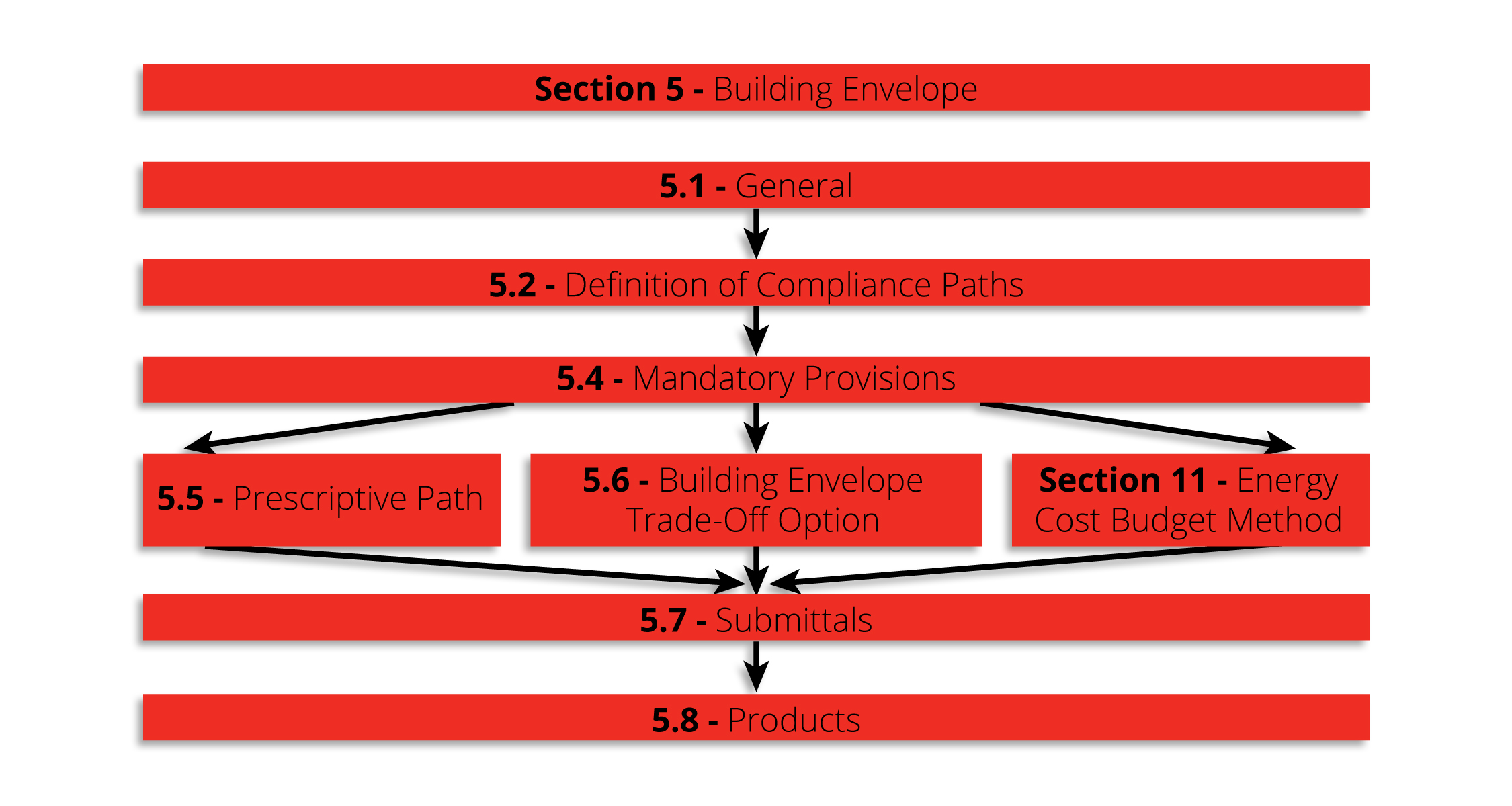
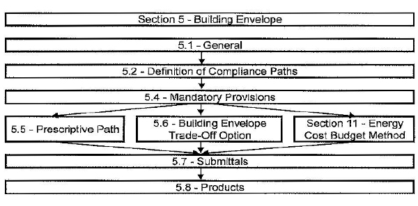
Are there any local code or project-specific stipulations as far as minimum R-values for the roof or for the walls? What must you be in compliance with? There can be many different aspects of an energy or building code that you will need to research. For example, there may be an envelope solution where the whole building nets out “X” R-value. Or, a prescribed method could be mandated, where each individual component (i.e., windows, doors, walls, etc.) going into that building cannot exceed (or must meet) a particular requirement.

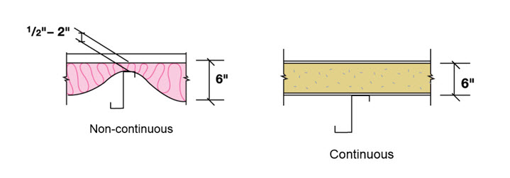
Let’s say, as an example, you have a code that requires you to have a continuous R-value at your structural attachment point. Depending on what that requirement is, it may be harder to achieve that by using a rolled or batt fiberglass systems. You might be able to achieve it much more easily with a componentized system using metal decking/liner and rigid board insulation, or perhaps an insulated metal panel (IMP) may be better suited. In that case, you could be looking at spending more money for that panel system while saving money on the labor … which brings us to the next variable: upfront costs.

Upfront Costs

Another critical factor is the cost associated with materials and labor of the system you’re going to install. Let’s say, for instance, your needs require a higher-end type installation in order to reach higher R-values or a code-prescribed method. How are you planning to achieve that?

In some instances, you may be looking toward an insulated panel system, which can readily give you those higher installed R-values. While these are extremely efficient systems, there can be a notable bump in the panel material price to get to that same level than if you choose a single-skin approach with a fiberglass or rigid board insulation system. You would, therefore, need to accurately compare the installed costs of the two systems versus just the material alone. Which will be less expensive/more efficient: the multiple components with lower individual costs plus more labor time and expense to assemble OR the potentially higher individual IMP panel price but with less time and expense to install? You will need to look at the project holistically to determine which is more cost-efficient for the specific situation.

Long-term costs, value and end-use functionality

Oftentimes, upfront material and labor costs need to be evaluated in terms of potential long-term savings and value. Some things to consider here are what your big picture needs are for the structure, including an assessment of how it will be used now and in the future. Unlike with dictated codes and regulations, here it may be more a question of wants vs. needs or owner-occupying vs. vendor leasing.

While you might want an R-30 building, for instance, is it economically beneficial for your end use of the building? Let’s use this example: If you’re a homeowner using a metal structure to store relatively non-valuable belongings, how well does it have to be insulated? Is it worth a high price point? In this case, perhaps single layer roof and wall insulation will be adequate for your needs.

If on the other hand, you’re a builder contracted to construct a structure for which interior climate control is critical for the end use—either because of the production to occur inside or perhaps due to food storage or other temperature-sensitive contents—then you might lean more toward an insulated panel system. In another example, if there’s going to be the potential for an abundance of heat or moisture in the building, as with paper products production or wastewater treatment, then you’ll want to be certain that the insulation system you use best resists such an interior climate and doesn’t permit condensation to form. In this example, it is critical that the structure is significantly protected so that moisture cannot become trapped in the roof or wall assemblies leading to reduced building efficiency or even formation of mold.

You should also consider how long it will take to recoup your initial investment. Obviously, for instance, you may spend less money upfront by only putting 4-inch blanket in your single layer metal walls as opposed to choosing to install an insulated metal panel (IMP) system, but long-term, is the money you save by going with the lesser insulation system going to be more than what the energy savings would be over the time that you’re the occupant of the building?

If you’re only going to be in the building for one or two years, or you’re not even occupying the building, you might be tempted to install a lesser expensive system, but then you might be risking not being able to retain tenants or impacting future resale value.

What Are the Insulation Options?

Once you’ve identified what the driving factors are for your insulation system choice, you can match up your needs with most popular options, which are:

Fiberglass insulation solutions, including over-the-purlin systems; cavity fill insulation systems; batt insulation; rigid board insulation via a composite system with metal decking and vapor barrier; or spray-on insulation systems. Alternatively, if a foam core insulation is preferred, it may be worth considering the use of insulated metal panels (IMPs) that are designed, engineered, and fabricated to be compatible with metal building construction as an envelope building solution.

For more specifics on the types of insulation systems that are available, check out this MBCI blog article: https://www.mbci.com/coordinating-roof-insulation-with-metal-building-construction/

Understanding LEED for Green Metal Buildings

Designing and constructing sustainable buildings has become a mainstream expectation of most building owners. Whether for reduced energy costs, higher returns on investment, or as an organizational philosophy, “green” building solutions are in demand. Perhaps the best known and most often cited program to achieve these goals is the US Green Building Council’s (USGBC’s) LEED® rating system. While some may think that green buildings are more complicated and costly to build, that is not actually the case. This is especially true when metal building materials are used. In fact, metal buildings are an ideal and economical way to pursue sustainability goals and LEED certification. How? We break it down as follows:

LEED

The LEED® Program

The LEED program has been in use since 1998 and is now used worldwide. It is a voluntary, point-based rating system that allows for independent review and certification at different levels. These levels include Certified (40-49 points), Silver (50-59 points), Gold (60-79 points), or Platinum (80 or more points). Since it allows for choices in which points are pursued, innovation and flexibility are entirely possible as long as specific performance criteria are met. It also encourages collaborative and integrative design, construction and operation of the building.

Points are organized into six basic categories, many of which can be addressed through metal building design and construction, as summarized below.

  • Location and Transportation: Metal buildings can be manufactured and delivered to virtually any location. That means they can support LEED criteria for being located near neighborhoods with diverse uses, available mass transit, bicycle trails, or other sustainable amenities. Metal building parking areas can also be designed to promote sustainable practices for green vehicles and reduced pavement. This all contributes toward obtaining LEED eligibility.
  • Sustainable Sites: Adding a building to any site will certainly impact the natural environment already there. Delivering portions of a pre-engineered metal building package in a sequence to arrive as needed means that the staging area on-site can be minimized—reducing site impacts. Additionally, using a “cool metal roof” has been shown to reduce “heat island” effects on the surrounding site and also qualify for LEED.
  • Water Efficiency: Any design that reduces or eliminates the need for irrigation of plantings and other outdoor water uses is preferred. Incorporating metal roofing with gutters and downspouts, as is commonly done on metal buildings, allows opportunities to capture rainwater for irrigation or other uses. It also helps control water run-off from the roof and assists with good storm water control.
  • Energy and Atmosphere: Metal buildings can truly shine in this category. Creating a well-insulated and air-sealed building enclosure is the most important and cost-effective step in creating an energy conserving building. A variety of insulation methods for metal building roof and wall systems are used to achieve this. Typically, metal building construction uses one or more layers of fiberglass insulation and liners combined with sealant and air barriers. Alternatively, insulated metal panels (IMPs) provide all of these layers in a single manufactured sandwich panel with impressive performance. Windows, skylights and translucent roof panels can provide natural daylight, allowing electric lighting to be dimmed or turned off. For buildings seeking to generate their own electricity,  standing-seam metal roofing provides an ideal opportunity for the simplified installation of solar photovoltaic (PV) systems. Metal roofs generally provide a sustainable service life in excess of 40 years. This means they can outlast the PV array, thus avoiding costly roof replacements during most PV array lifespans.
  • Materials and Resources: Life Cycle Assessments (LCAs) are recognized by LEED as the most effective means to holistically assess the impacts that materials and processes have on the environment and on people. Fortunately, the Metal Building Manufacturer’s Association (MBMA) has collaborated with the Athena Sustainable Materials Institute and UL Environment to develop an industry-wide life cycle assessment report. There is also an Athena Impact Estimator that can help with providing LEED documentation. Metal buildings support exceptional environmental performance through the significant use of recycled steel and the reduced need for energy intensive concrete due to lighter weight buildings.
  • Indoor Environmental Quality: Most people spend much more time indoors than outside, which impacts human health. Therefore, LEED promotes or requires using materials that don’t contain or emit harmful substances. It also promotes design options for natural daylight, exterior views and acoustical control to promote psychological and emotional well-being. Metal buildings are routinely designed to readily incorporate components that help achieve these indoor qualities.

In addition, some LEED points are available for demonstrating innovation and addressing priorities within a geographic region.

Considering the qualities listed above, metal buildings clearly provide a prime opportunity to pursue LEED certification at any level. To find out more about the LEED rating system, visit https://new.usgbc.org/leed. To find out more about successfully designing and constructing metal buildings pursuing LEED certification, contact your local MBCI representative.

Proper Test Methods to Determine Thermal Resistance of Metal Panels

For a given assembly, if the right information is not specified in conjunction with the desired R-value, the designer will likely not achieve the results he or she expects. This can lead to code compliance issues as well as poor performance of the finished building. Therefore, a more thorough approach must be considered to ensure the specified assembly will be building energy efficiency code compliant. Where to begin? When looking at proper test methods to determine thermal resistance of metal panels, the place to start is ASHRAE 90.1 Chapter 5 (Building Envelope) and Appendix A.

Thermal Resistance
ASHRAE 90.1 Section 5 specifies requirements for the building envelope.

Code Compliance for Thermal Resistance

The most widely accepted energy efficiency standard for commercial construction in North America is ASHRAE Standard 90.1. This standard provides both a prescriptive and a performance path to be chosen at the designer’s option. The prescriptive path is most commonly used. It also provides the baseline performance level that is used to determine compliance for the performance path, so understanding this set of requirements is critical. Within the prescriptive path, two possible methods of compliance are available to determine the minimum thermal performance of opaque areas on the building envelope. Section 5.5.3 is the pertinent passage and it reads:

  1. Minimum rated R-values of insulation for the thermal resistance of the added insulation in framing cavities and continuous insulation only. Specifications listed in Normative Appendix A for each class of construction shall be used to determine compliance.
  2. Maximum U-factor, C-factor, or F-factor for the entire assembly. The values for typical construction assemblies listed in Normative Appendix A shall be used to determine compliance.

Exceptions: For assemblies significantly different than those in Appendix A, calculations shall be performed in accordance with the procedures required in Appendix A.

What does this mean? Basically, there are standard types of construction that ASHRAE recognizes and if you have a wall that fits the description in Appendix A, you don’t have to test or do anything special to determine its thermal resistance. Appendix A provides tables based on calculation methods that have been derived on the basis of previous tests and general experience. What is perhaps less obvious is that if your assembly is adequately described by one of the standard assemblies in the Appendix, you may NOT use a tested or modeled value in place of the values in the table, even if that value has better performance! (i.e., lower U-factor) This is explained in Section A1.2.

The reason the code is set up this way is to prevent people from building unrepresentative assemblies that achieve high performance in the lab but are likely not built to the same specifications in the actual building.

Conversely, if the assembly you want to use is NOT adequately described in Appendix A, the appendix goes on to specify which methods are acceptable to determine the U-factor based on the assembly to which it is most similar. This is covered in Section A9. Two and three-dimensional finite element models are always acceptable and in some cases, simplified calculation alternatives are also available. Note that hot box testing is not always allowed.

Conclusion

To summarize, whether using a prescriptive or a performance path, the first and last stop when determining thermal resistance for metal panels is ASHRAE Standard 90.1 Chapter 5 and Appendix A. Designers would be well advised to familiarize themselves with the Standard and the specific set of requirements for their particular scenario in order to utilize proper testing methods for high-performance results.

Understanding R-Values and K-Factors in Considering Thermal Resistance

Described in their most basic terms, R-value is a measure of heat resistance, while U-factor (also know as U-value) is a measure of heat transfer (heat gain or loss). The lesser known K-factor is simply the reciprocal of the R-value of the insulation divided by the thickness. What they all have in common is a relationship to the effectiveness of insulation material in resisting heat flow through a roof or wall element. There are different ways that this would be spec’d from a manufacturer to an architect or engineer. While the terminology might be familiar, the specifics are not always as clear cut as they seem. Understanding the differences will allow architects to make smart and effective choices to suit a given project’s needs.

Let’s consider some of the variables that might have an impact on what to look for and which metric to spec. As means of illustration, put yourself in the shows of a fiberglass or insulation supplier. You have a product, you know what it’s rated to, you know what the performance capability is, it’s been spec’d out to you—and you submit the bid based on those factors. But at that point you inevitably lose control over how the specs would actually get implemented. For instance, the architect may take that spec and incorporate it into a wall where it’s not used the most efficient way. This may not even be the result of a mistake; it could just be that other project elements have taken over.

Factor
Choosing the right insulation for the project can provide the building significant energy savings.

A good example would be stud walls. The fiberglass insulation supplier might indicate a given R-value, such as R-19. This would be the heat resistance value. The architect might spec and submit that bid to supply x number of square feet of that insulation based on that R-value. However, it could be cut or delivered in rolls and designed to fit between the metal studs. Metal studs are much more conductive than insulation and they provide an alternate path for the heat to flow through the assembly, almost irrespective of what the R-value and insulation is. Given these factors, the architect might have to make tradeoffs.

Choosing U-Factor

Because of all the variables encountered with R-value, U-factor is actually more recommended and reliable, and it more appropriately meets code requirements.* The concept of U-factor relates to the heat transfer coefficient but is described in the code as total heat flow per unit area through the assembly inclusive of all the short circuits as it is planned out to be built. So, an architect or engineer would know the stud spacing, the cladding material, the interior finish material and the R-value of the insulation. With that information in hand, one can go to a textbook, ASHRAE 90.1 or the ASHRAE Book of Fundamentals and find the U-factor for the assembly. It is this U-factor that is actually compared against the code requirements. It’s a better way to spec because it already takes into consideration all those things that come into play and encourages the use of suppliers (such as MBCI) that staff people who can help do those calculations or give assistance as opposed to saying, “I need R-19” and then wind up with a building that’s bridged or has more short circuits than anticipated—and having the building not perform as needed. This, in essence, is the key difference between R-value and U-factor.

A Word About K-Factor

As for K-factor, as noted this is the thickness of the insulation divided by the R-value. Its intention is to spec out an insulation when you’re not entirely sure what thickness it will be at the time you spec it out. This is fine for design-build scenarios but not a good practice for a hard bid. Bottom line: U-factor is most often the most reliable choice.

*Note: The code defines U-factor as discussed but underlying heat transfer theory may describe U-factor as 1/R-value. Insualtion suppliers might invert it and make it an R-value (but doesn’t take all the variables into consideration). Therefore, an architect would be advised to specify a “U-factor in compliance with ASHRAE, ” which includes thermal bridges, joints, etc.

Combatting Thermal Bridging with Insulated Metal Panels

When using compressible insulation, say for instance fiberglass batt, consideration must be given to how that insulation is going to be deployed in the actual wall or roof. For instance, installers might place the insulation across the framing members and then smash it down with the cladding and run a screw through to the underlying structure. The problem here is that the insulation is rated with some R-value—and that R-value is determined by an ASTM procedure that also determines what its tested density is. So in essence, it’s ‘fluffy’ insulation.

One manufacturer’s insulation, however, might be thicker than another’s. The contractor is buying an R-value, not a density or a thickness. The insulation is tested to that R-value at whatever thickness and density¹ is needed to achieve it. Let’s say R-19 fiberglass batt is specified, but then it is put in an assembly and smashed down flat… now it’s not R-19 anymore; it’s now R-something else. That’s a thermal bridge—when the insulation’s R-value has been compromised.

Manufacturers have the ability to run long length panels that minimize the number of end joints. This continuity provides significant advantages over traditional insulated materials when designing for energy efficiency. This image illustrates the difference between fiberglass batting made discontinuous by compression between panel and framing members and the continuous insulation provided by insulated metal panels.

Unfortunately, thermal bridging is almost impossible to eliminate. In the example above, another choice might be to put it between studs. Except in this situation, the studs break the insulation. While it’s not pinched, the studs are separating it. Whether the studs are metal or wood, in either case it’s still a significant thermal short circuit or a thermal bridge.

Even with the highest quality insulation systems—insulated metal panels, for example—a joint is required. Building is not possible without putting neighboring panels together. Therefore, insulation is discontinuous. While it’s impossible to avoid thermal bridging, there are two requirements to ensure the building performs the way it needs to perform.

  1. Thermal bridging must be mitigated. In other words, the designer or installer has to try to eliminate as much of it as possible.
  2. If thermal bridging is unavoidable, it must be accounted for in some fashion, which usually means putting more insulation somewhere to make up the difference. This is called a “trade-off” and is allowed by most building energy efficiency codes.²

Why Insulated Metal Panels?

Insulated metal panels then are the best bet, because although the joint is a thermal bridge, in effect, it is not nearly as impactful as breaking a line of fiberglass with a stud or smashing the fiberglass between the panel and a framing member. In the illustration below, R-value doesn’t just vary at that point where the panel and the stud meet. The entire insulation line gets smashed and one would have to go some distance from the stud before the insulation returns to its normal, fluffy thickness. These issues need to be mitigated and accounted for.

assembled side joint
Continuous insulation is critically important to an efficient envelope design. Insulated metal panels, with their side laps designed for concealed fasteners, eliminate the possibility of gaps in the insulation and thermal bridges. Continuous insulation is important because thermal bridges and discontinuities introduced by compressing non-rigid insulations cause the in-place R-Value of the assembly to be less than the tested R-Value of the insulation used. This effect has become a focus in newer energy efficiency codes such as ASHRAE 90.1 and IECC.

Manufacturers such as MBCI and Metl-Span publish insulated metal panels as U-factors because the joint is tested as part of the assembly (both mitigating and accounting for the aforementioned issues). These values can be found on product data sheets and technical bulletins, such as Metl-Span’s Insulation Values technical bulletin, published January 2017.

References

  1. ASTM C 665 – 12, Standard Specification for Mineral-Fiber Blanket Thermal Insulation for Light Frame Construction and Manufactured Housing, Table 1, Footnote c.
  2. ASHRAE 90.1 – 13, Energy Standard for Buildings Except Low-Ride Residential Buildings, Section 5.6
  3. High Performance Green Building Products – INSMP2A (CEU)

Calculating Cool Roof Energy Savings

Whether it’s providing waterproofing, reducing thermal expansion and contraction, or supplying chemical and damage protection, cool metal roofing has much to offer. Of course, the most substantial benefit is the energy savings gleaned from reduced rooftop heat levels driving down air conditioning loads. In fact, the Lawrence Berkeley National Laboratory’s heat island group projects a whopping $1 billion reduction in cooling costs if cool roofs were to be implemented on a nationwide basis.

To assist architects in determining the kinds of energy savings that can be expected from cool metal roofing, the Oak Ridge National Laboratory (ORNL) has parlayed the data it gathered from a three-year evaluation of metal roofing products into a whole building energy savings calculator.

Cool metal roofs are offered in a variety of colors.
In addition to energy efficiency, cool metal roofs are known for extended durability and longevity.

Cool Roof Calculator

This calculator is called, simply enough, the Cool Roof Calculator. The easy-to-use tool is described as a quick way to compare overall energy costs and savings for a variety of roof and building conditions. Unlike some energy modeling calculators, which are limited to steep slope residential roofs with attics, ORNL’s tool models the typical low slope commercial roof with insulation placed directly over the deck and under the roofing membrane.

To calculate approximate energy savings offered by a cool metal roof, architects are instructed to input the building’s location, proposed roof R-value, roof reflectance and emittance, base energy costs, equipment efficiencies, electrical demand charges and duration.

While experts suggest that it may be difficult to accurately predict the base use and peak demand without detailed construction and cost information, tools such as the ORNL’s cool roof calculator can be a useful way to gather helpful performance estimations for a variety of building types and locations.

Attempting to do just that, the calculator outputs a number of values to offer an approximate estimate of potential energy savings, broken down into cooling energy savings—a calculation of air conditioning savings from base use and peak demand reductions—and cooling season demand savings, an estimate of the peak demand charge reduction enabled by enhanced roof reflectivity.

Accessible at http://rsc.ornl.gov, users can also compare the energy performance offered by a cool roof vs. a conventional black roof.

“It’s a nice tool to give people a feel for where a cool roof would actually help them and have the greatest impact in terms of energy use,” relates Robert A. Zabcik, PE, LEED AP BD+C, director, research and development, NCI Group Inc., Houston, in a Metal Construction News article.

Roof Reflectance Baseline

Roof reflectance and emittance, requirements and options, can be found in energy codes such as IECC, ASHRAE 90.1, California Title 24, and other local codes. Requirements may vary based on roof slope and climate zone, and may allow for either aged or initial solar reflectance, thermal emittance and/or SRI.

Fortunately, MBCI continues to stay current with individual testing and also maintains third-party tested and verified product listings through entities such as the Cool Roof Rating Council, and the U.S. EPA’s ENERGY STAR®.

Thermal Bow vs. Thermal Expansion: A Look at Thermal Efficiency in Insulated Metal Panels

Insulated metal panels  (IMPs), a type of lightweight factory-fabricated metal panel,  are a compelling alternative to more conventional roof panel choices. IMPs have a continuous insulating core that works together with metal skins to create a barrier against air, water vapor, and thermal conditions. One major benefit of IMPs, is their thermal efficiency, averaging R-7.0 to 7.2 per inch as compared to R-5.6 per inch for unfaced urethane board stock. Insulated metal roof panels are commonly available in thicknesses ranging from two- to six-inches which generally correlates to R-14 to 42.

Structure of IMPs

IMPs consist of two single skin metal panels and a foamed-in-place core. The foam insulation is made of non-chlorofluorocarbon (non-CFC) polyurethane foam. As an example, MBCI’s IMPs consist of closed cell structure and nominal density of 2.2 pounds per cubic foot. Its closed cell structure also prevents the foam from absorbing water.

Thermal Bow in IMPs

Thermal Efficiency of IMPs
Thermal expansion of insulated metal panels is accommodated by thermal bowing.

An interesting phenomenon with IMP roof panels is that you don’t have to deal with thermal expansion the way you do with single skin panels. On wide, through-fastened roofs, you can have issues with panels slotting around the fasteners. And with standing seam roofs, you have to ensure that the panel clips can handle the anticipated thermal movement. However, insulated panels experience something called “thermal bow.”

An IMP’s exterior metal skin will still expand as it heats up. But, instead of causing the whole IMP to grow in length,  the exterior skin of the IMP will bow up slightly between purlins/joists because the interior metal skin of the IMP maintains a relatively constant temperature. The insulating foam that adheres to this metal skin flexes to allow for this bow. Because of this, thermal expansion is accommodated by the small incremental growth (and bowing up) of the exterior metal skin between each purlin/joist, which are usually spaced five to seven feet apart.

­­­­­Conclusion

Insulated metal roof panels are fixed roof systems that will experience thermal bow between the purlins as opposed to single skin systems, which are designed to allow for expansion and contraction in the panel. With its thermal efficiency benefits, IMP roofs are beginning to get noticed as an alternative for designers looking for a progressive choice to achieve flexibility and function.

A Common Misconception About Determining Thermal Resistance

metal roofing r value
Photo courtesy of the U.S. Department of Energy

As an architect, you’re required to design a building’s wall to meet the code-required R-value (or U-factor) in the International Energy Conservation Code. So you design the wall and add up the manufacturer-stated R-values of the components.  Done, right? That method only makes sense if walls have no joints, seams, windows, or doors! Let’s think about this.

Accounting for Thermal Discontinuities

The manufacturer-stated R-value of an insulated metal panel (IMP) should really be the R-value in the center portion of the panel, if the manufacturer uses terminology consistent with ASHRAE 90.1. However, a wall is made up of many IMPs, and there are joints between the IMPs.  We’ve all seen the infrared photos showing the heat loss at joints between panelized anything—plywood, insulation boards…and IMPs. The joints between each and every IMP are thermal discontinuities, commonly called thermal bridges. These are locations where the R-value is not what you read in the manufacturer’s literature. There are also metal clips and attachments that reduce the R-value of the IMP wall system. If you’re designing a wall system, don’t specify the R-value of the panel and assume it is the R-value of the wall system!

Calculating the R-Value of a Complete IMP System

A building owner deserves a wall that meets or exceeds the code-required minimum R-value or U-factor. The mechanical engineer needs to properly size the building’s mechanical systems based on the ‘real’ characteristics of the building envelope.

Let’s put some numbers behind this idea. Let’s consider a 42 inch-wide panel, 2 inches thick, with a stated R-value of 12. The outer surface of the panel is close to the exterior temperature—say 30 degrees. The metal wraps through the joint, decreasing the temperature of a portion of the metal on the backside of the panel everywhere there is a joint. Clearly this reduces the overall R-value of the IMP as a system.  Let’s estimate that the thermal bridging effect of the joints reduces the R-value 5 inches along the edges of the panels to an R-6. That means 30 inches of the panel has an R-12, and 10 inches of the panel has an R-6. That calculates to an average R-value of 10.5 for the panel overall, which is more than a 12% loss of R-value. This is why blindly using the famous equation of R=1/U is dangerous. That equation is only true if the R-value and U-factor involved are consistent with how thermal bridging is or isn’t represented.

U-Factor Testing for Higher Accuracy

It’s clear that the panel joints are thermal bridges, but the extent of loss is really an educated guess. But there is a solution! The forward-thinking IMP manufacturers are performing U-factor testing and finite element modeling, and that includes joints between panels. The U-factor testing is a more accurate determination of thermal resistance.

As an architect designing the wall system, if you use stated R-values, recognize that you’ll need to account for the loss of R-value because of the joints. Or, simply specify panels whose manufacturers are determining the U-factor for their IMPs!

Wellness and Envelopes: Four Ways Single Skin & Insulated Metal Panels Keep Us Healthy

SONY DSC


Is there a connection between building design and human health?

We know the answer must be yes, but figuring out how the connection works is the job of experts like the team behind the WELL Building Standard®, a new certification that takes on the question. Among the solutions that can help make a building better? Metal roofing and siding, according to many healthy building experts.

First, let’s learn about WELL. According to the International WELL Building Institute, the WELL Building Standard “takes a holistic approach to health in the built environment addressing behavior, operations and design.” Their performance-based system measures and monitors such building features as air, water, nourishment, light, fitness, comfort, and mind. Two ratings have been offered: WELL Certified™ spaces and WELL Core and Shell Compliant™ developments. Done properly, these “improve the nutrition, fitness, mood, sleep patterns, and performance of occupants.”

Pilot programs are currently available for retail, multifamily residential, educational, restaurants and commercial kitchens projects. In many of these projects, the use of metal claddings and insulated metal panels (IMPs) is recommended by many health-focused professionals. Why?

1. Occupant comfort

IMPs tend to have excellent R-values and very good thermal efficiency – including long-term thermal resistance, or LTTR, a key measure of how the building will perform over time. For the wellness factor from pure thermal comfort, IMPs are highly effective over conventional construction.

2. Nourishment of people and earth

IMPs are often made with recycled metals and improve the energy performance of the building. With energy cost savings ranging from 5 percent to 30 percent, they cut the carbon footprint of the facility. Plus the interior and exterior skins include up to 35 percent recycled content – and they are 100 percent recyclable – reducing impact on the global carbon load.

3. Daylight for all.

Using metal roofs with skylights or light-transmitting panels in conjunction with integrated dimming lighting is a highly cost-effective strategy, and IMP systems also have integrated window systems that increase available sunlight within building interiors. Light is essential for healthy buildings, and daylight is the best kind of all.

In addition, because rigid insulation per inch offers more R-value than per inch of fiberglass insulation and IMPs have metal liner skins, day-lighting fixtures such as light tubes can be integrated more easily with these roofs.

4. Proper moisture and air control.

Issues such as leaky walls and wet, moldy construction materials are anathema to wellness, and must be controlled for healthy building certifications. Mold has a negative impact on indoor air quality and indoor environmental quality, and one of the main culprits is trapped moisture. This can also corrode the metal studs and furring members, even if they are galvanized, leading to structural issues such as reduced fastener pullout resistance and leaks.

How Does a Building Become WELL Certified?

IMPs used as either rainscreens or as sealed barrier walls backing up a rainscreen are shown to protect against moisture issues and mold over time. They also serve as a continuous layer of insulation and air barrier. In this way, the single-component system can eliminate the need “for air barriers, gypsum sheathing, fiberglass insulation, vapor barriers, and other elements of a traditional multicomponent wall system,” says one industry executive. In fact, many masonry buildings are being upgraded with IMP retrofits on the exterior, directly over the old concrete, brick or stone.

All of these traits of IMPs certainly contribute to more healthy buildings, but do they add up to WELL Building certification levels, such as Silver, Gold or Platinum?

To get there, building teams must undergo an on-site WELL Commissioning process with rigorous post-occupancy performance testing of all the features. If it meets the “preconditions” — the WELL features necessary for baseline certification — WELL Certification is given. If the team pursues “optimization features,” the higher levels of achievement are granted.

Sustainability Begets Resiliency…In Practice

McMahaon Centennial Complex, Cameron University

Sustainability is the buzzword started by USGBC that is pushing us to design and build environmentally friendly buildings.  And that’s a good thing.  However, from a practical—and roofing—standpoint, what we can most readily do with roofs is design them to be resilient.  Roof system resiliency is the tangible aspect of sustainability that the “regular” population can get their heads around.  Resiliency—the ability to bounce back—is understandable.

Loosely speaking, a resilient building can withstand an extreme weather event and remain habitable and useful.  It follows that a resilient roof system is one that can withstand an extreme weather event and continue to perform and provide shelter.

What makes a metal roof system resilient?  It needs to be tough and durable, wind and impact resistant, highly insulated and appropriately reflective, and perhaps be a location for energy production.

An extreme weather event typically means high winds.  A resilient metal roof system needs to withstand above-code wind events.  Remember, codes are minimum design requirements; there is nothing stopping us from designing metal panel roofs above code requirements!  If a building is located in a 120 mph wind zone, increase the design/increase the attachment as if it were in a 140 mph wind zone.  And, very importantly, increasing the wind resistance of the edge details is critical to the wind resistance of a roof system.

Toughness is important.  Increasing the thickness of a metal panel roof system increases resistance to impacts and very likely increases service life (of the metal panel, at least).  Tough and durable seams are important, too.  A double-lock standing seam is one of the best seam types for metal roofs.  A little bit of extra effort at the seam can go a long way for durability, weatherproofing, and longevity.

Highly insulated and appropriately reflective are also traits of resiliency.  High R-value means less thermal transfer across the roof assembly.  Two layers, staggered or crisscrossed, provide a thermally efficient insulation layer.  Using thermal breaks between the metal panels and the metal substructure adds to the thermal efficiency.  Reflective roofs help reduce heat transfer through the roof assembly.  The effectiveness of a roof’s color and reflectivity to save energy depends on many items, such as location, stories, and building type.

Enhanced wind resistance, improved impact resistance and toughness, high R-value, and reflectivity and color are passive design elements that increase the resiliency of a building’s rooftop.  And let’s not forget that rooftop energy production can provide electricity to critical components of a building, such as a freezer section of a grocery store.  Hurricane Sandy put resiliency on the public radar; resilient buildings are here to stay.

Find a sales representative