As an architect, you’re required to design a building’s wall to meet the code-required R-value (or U-factor) in the International Energy Conservation Code. So you design the wall and add up the manufacturer-stated R-values of the components. Done, right? That method only makes sense if walls have no joints, seams, windows, or doors! Let’s think about this.
Accounting for Thermal Discontinuities
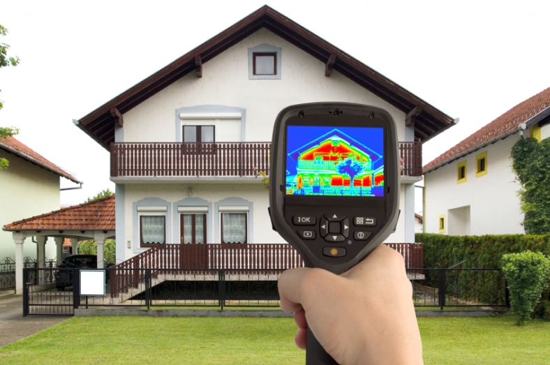
The manufacturer-stated R-value of an insulated metal panel (IMP) should really be the R-value in the center portion of the panel, if the manufacturer uses terminology consistent with ASHRAE 90.1. However, a wall is made up of many IMPs, and there are joints between the IMPs. We’ve all seen the infrared photos showing the heat loss at joints between panelized anything—plywood, insulation boards…and IMPs. The joints between each and every IMP are thermal discontinuities, commonly called thermal bridges. These are locations where the R-value is not what you read in the manufacturer’s literature. There are also metal clips and attachments that reduce the R-value of the IMP wall system. If you’re designing a wall system, don’t specify the R-value of the panel and assume it is the R-value of the wall system!
Calculating the R-Value of a Complete IMP System
A building owner deserves a wall that meets or exceeds the code-required minimum R-value or U-factor. The mechanical engineer needs to properly size the building’s mechanical systems based on the ‘real’ characteristics of the building envelope.
Let’s put some numbers behind this idea. Let’s consider a 42 inch-wide panel, 2 inches thick, with a stated R-value of 12. The outer surface of the panel is close to the exterior temperature—say 30 degrees. The metal wraps through the joint, decreasing the temperature of a portion of the metal on the backside of the panel everywhere there is a joint. Clearly this reduces the overall R-value of the IMP as a system. Let’s estimate that the thermal bridging effect of the joints reduces the R-value 5 inches along the edges of the panels to an R-6. That means 30 inches of the panel has an R-12, and 10 inches of the panel has an R-6. That calculates to an average R-value of 10.5 for the panel overall, which is more than a 12% loss of R-value. This is why blindly using the famous equation of R=1/U is dangerous. That equation is only true if the R-value and U-factor involved are consistent with how thermal bridging is or isn’t represented.
U-Factor Testing for Higher Accuracy
It’s clear that the panel joints are thermal bridges, but the extent of loss is really an educated guess. But there is a solution! The forward-thinking IMP manufacturers are performing U-factor testing and finite element modeling, and that includes joints between panels. The U-factor testing is a more accurate determination of thermal resistance.
As an architect designing the wall system, if you use stated R-values, recognize that you’ll need to account for the loss of R-value because of the joints. Or, simply specify panels whose manufacturers are determining the U-factor for their IMPs!