Proper Test Methods to Determine Thermal Resistance of Metal Panels

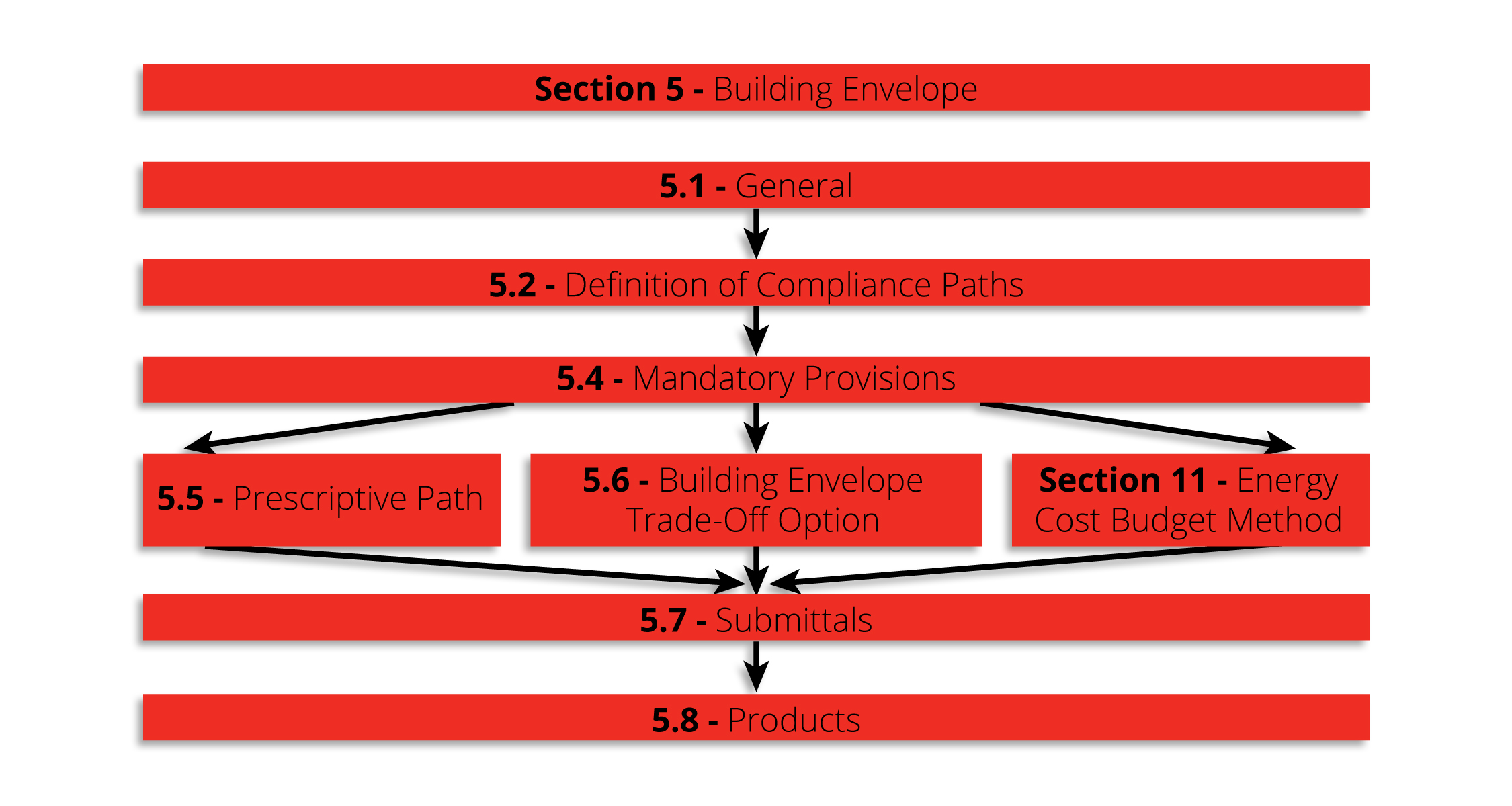
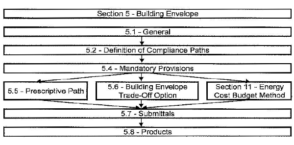
For a given assembly, if the right information is not specified in conjunction with the desired R-value, the designer will likely not achieve the results he or she expects. This can lead to code compliance issues as well as poor performance of the finished building. Therefore, a more thorough approach must be considered to ensure the specified assembly will be building energy efficiency code compliant. Where to begin? When looking at proper test methods to determine thermal resistance of metal panels, the place to start is ASHRAE 90.1 Chapter 5 (Building Envelope) and Appendix A.

Thermal Resistance
ASHRAE 90.1 Section 5 specifies requirements for the building envelope.

Code Compliance for Thermal Resistance

The most widely accepted energy efficiency standard for commercial construction in North America is ASHRAE Standard 90.1. This standard provides both a prescriptive and a performance path to be chosen at the designer’s option. The prescriptive path is most commonly used. It also provides the baseline performance level that is used to determine compliance for the performance path, so understanding this set of requirements is critical. Within the prescriptive path, two possible methods of compliance are available to determine the minimum thermal performance of opaque areas on the building envelope. Section 5.5.3 is the pertinent passage and it reads:

  1. Minimum rated R-values of insulation for the thermal resistance of the added insulation in framing cavities and continuous insulation only. Specifications listed in Normative Appendix A for each class of construction shall be used to determine compliance.
  2. Maximum U-factor, C-factor, or F-factor for the entire assembly. The values for typical construction assemblies listed in Normative Appendix A shall be used to determine compliance.

Exceptions: For assemblies significantly different than those in Appendix A, calculations shall be performed in accordance with the procedures required in Appendix A.

What does this mean? Basically, there are standard types of construction that ASHRAE recognizes and if you have a wall that fits the description in Appendix A, you don’t have to test or do anything special to determine its thermal resistance. Appendix A provides tables based on calculation methods that have been derived on the basis of previous tests and general experience. What is perhaps less obvious is that if your assembly is adequately described by one of the standard assemblies in the Appendix, you may NOT use a tested or modeled value in place of the values in the table, even if that value has better performance! (i.e., lower U-factor) This is explained in Section A1.2.

The reason the code is set up this way is to prevent people from building unrepresentative assemblies that achieve high performance in the lab but are likely not built to the same specifications in the actual building.

Conversely, if the assembly you want to use is NOT adequately described in Appendix A, the appendix goes on to specify which methods are acceptable to determine the U-factor based on the assembly to which it is most similar. This is covered in Section A9. Two and three-dimensional finite element models are always acceptable and in some cases, simplified calculation alternatives are also available. Note that hot box testing is not always allowed.

Conclusion

To summarize, whether using a prescriptive or a performance path, the first and last stop when determining thermal resistance for metal panels is ASHRAE Standard 90.1 Chapter 5 and Appendix A. Designers would be well advised to familiarize themselves with the Standard and the specific set of requirements for their particular scenario in order to utilize proper testing methods for high-performance results.

How Energy Codes Influence Metal Roof Panel Selection

On a very basic level, specifiers can look at a climate zone map and get an idea of the metal roof panel best suited to a specific geographic region. The issue, however, is actually much more complex. One must know that overlooking any detail could result, not only in less-than-ideal performance, but also in costly project fail, often related to the project not meeting required energy codes or other standards. With this in mind, an important initial question to consider is how to select metal roof panels that conform to new and fast-changing energy codes and their designated climate zones.

To begin making wise considerations, the architect must know what codes are in play. For instance, is it IECC or ASHRAE 90.1? Which year of the code/standard? Are there additional local code requirements? Even if a state adopts a particular energy code, it doesn’t necessarily mean that all jurisdictions will adopt the code at the same time. Along with this, some local jurisdictions may have their own or additional requirements. To be successful, it is imperative to know what the regional project goals and requirements are. This will require research prior to specifying the metal roof panel and its assembly.

Using IECC and ASHRAE 90.1 for Energy Code Compliance

Three of the basic metal building roof panel types are single-skin standing seam, screw-down and insulated metal panels (IMPs). When using the tables in IECC and ASHRAE 90.1 for metal building roofs it must be remembered that these tables are based on single-skin standing seam roof panels and purlins that are 5′ on center. The tables provide the required R-values and/or U-factors based on climate zones, along with other assembly requirements noted with each tables. In the Appendix of some versions of ASHRAE 90.1, there are allowances for modified roof assemblies, including screw-down metal roofs.

Energy Code
DOE-Developed Climate Zone Map

Often, in certain climate zones, the required R-values and U-factors may be so stringent that the logical first consideration is to use insulated metal panels. IMPs are a great choice for offering high insulation properties in a top-of-the-line product and the R-values and U-factors are readily available for use in compliance calculations.

Keep in mind when deviating from the prescribed assemblies in IECC and ASHRAE 90.1, calculations will be required to show compliance, along with modeling and/or the use of approved compliance software, such as COMcheck.

Making Informed Decisions

Selecting the right metal roof panel is an important step to achieving energy code compliance. Even though energy codes can be complex and are constantly evolving, by making informed metal roof panel selections you will add to the overall success of your project.


Top Five Tips:

  • Know your code. Find out what energy code is required for your project.
  • Know your zone. Requirements vary by climate zone. Identify your project’s climate zone.
  • Understand your options. Deviating from specified assemblies will require approved proof of compliance.
  • Choose wisely. Research the properties and assembly requirements of any metal roof panel. Use this information in conjunction with energy code requirements to make wise choices.
  • Call with questions. Call the manufacturer with questions before you get too far down the road.

Understanding R-Values and K-Factors in Considering Thermal Resistance

Described in their most basic terms, R-value is a measure of heat resistance, while U-factor (also know as U-value) is a measure of heat transfer (heat gain or loss). The lesser known K-factor is simply the reciprocal of the R-value of the insulation divided by the thickness. What they all have in common is a relationship to the effectiveness of insulation material in resisting heat flow through a roof or wall element. There are different ways that this would be spec’d from a manufacturer to an architect or engineer. While the terminology might be familiar, the specifics are not always as clear cut as they seem. Understanding the differences will allow architects to make smart and effective choices to suit a given project’s needs.

Let’s consider some of the variables that might have an impact on what to look for and which metric to spec. As means of illustration, put yourself in the shows of a fiberglass or insulation supplier. You have a product, you know what it’s rated to, you know what the performance capability is, it’s been spec’d out to you—and you submit the bid based on those factors. But at that point you inevitably lose control over how the specs would actually get implemented. For instance, the architect may take that spec and incorporate it into a wall where it’s not used the most efficient way. This may not even be the result of a mistake; it could just be that other project elements have taken over.

Factor
Choosing the right insulation for the project can provide the building significant energy savings.

A good example would be stud walls. The fiberglass insulation supplier might indicate a given R-value, such as R-19. This would be the heat resistance value. The architect might spec and submit that bid to supply x number of square feet of that insulation based on that R-value. However, it could be cut or delivered in rolls and designed to fit between the metal studs. Metal studs are much more conductive than insulation and they provide an alternate path for the heat to flow through the assembly, almost irrespective of what the R-value and insulation is. Given these factors, the architect might have to make tradeoffs.

Choosing U-Factor

Because of all the variables encountered with R-value, U-factor is actually more recommended and reliable, and it more appropriately meets code requirements.* The concept of U-factor relates to the heat transfer coefficient but is described in the code as total heat flow per unit area through the assembly inclusive of all the short circuits as it is planned out to be built. So, an architect or engineer would know the stud spacing, the cladding material, the interior finish material and the R-value of the insulation. With that information in hand, one can go to a textbook, ASHRAE 90.1 or the ASHRAE Book of Fundamentals and find the U-factor for the assembly. It is this U-factor that is actually compared against the code requirements. It’s a better way to spec because it already takes into consideration all those things that come into play and encourages the use of suppliers (such as MBCI) that staff people who can help do those calculations or give assistance as opposed to saying, “I need R-19” and then wind up with a building that’s bridged or has more short circuits than anticipated—and having the building not perform as needed. This, in essence, is the key difference between R-value and U-factor.

A Word About K-Factor

As for K-factor, as noted this is the thickness of the insulation divided by the R-value. Its intention is to spec out an insulation when you’re not entirely sure what thickness it will be at the time you spec it out. This is fine for design-build scenarios but not a good practice for a hard bid. Bottom line: U-factor is most often the most reliable choice.

*Note: The code defines U-factor as discussed but underlying heat transfer theory may describe U-factor as 1/R-value. Insualtion suppliers might invert it and make it an R-value (but doesn’t take all the variables into consideration). Therefore, an architect would be advised to specify a “U-factor in compliance with ASHRAE, ” which includes thermal bridges, joints, etc.

A Common Misconception About Determining Thermal Resistance

metal roofing r value
Photo courtesy of the U.S. Department of Energy

As an architect, you’re required to design a building’s wall to meet the code-required R-value (or U-factor) in the International Energy Conservation Code. So you design the wall and add up the manufacturer-stated R-values of the components.  Done, right? That method only makes sense if walls have no joints, seams, windows, or doors! Let’s think about this.

Accounting for Thermal Discontinuities

The manufacturer-stated R-value of an insulated metal panel (IMP) should really be the R-value in the center portion of the panel, if the manufacturer uses terminology consistent with ASHRAE 90.1. However, a wall is made up of many IMPs, and there are joints between the IMPs.  We’ve all seen the infrared photos showing the heat loss at joints between panelized anything—plywood, insulation boards…and IMPs. The joints between each and every IMP are thermal discontinuities, commonly called thermal bridges. These are locations where the R-value is not what you read in the manufacturer’s literature. There are also metal clips and attachments that reduce the R-value of the IMP wall system. If you’re designing a wall system, don’t specify the R-value of the panel and assume it is the R-value of the wall system!

Calculating the R-Value of a Complete IMP System

A building owner deserves a wall that meets or exceeds the code-required minimum R-value or U-factor. The mechanical engineer needs to properly size the building’s mechanical systems based on the ‘real’ characteristics of the building envelope.

Let’s put some numbers behind this idea. Let’s consider a 42 inch-wide panel, 2 inches thick, with a stated R-value of 12. The outer surface of the panel is close to the exterior temperature—say 30 degrees. The metal wraps through the joint, decreasing the temperature of a portion of the metal on the backside of the panel everywhere there is a joint. Clearly this reduces the overall R-value of the IMP as a system.  Let’s estimate that the thermal bridging effect of the joints reduces the R-value 5 inches along the edges of the panels to an R-6. That means 30 inches of the panel has an R-12, and 10 inches of the panel has an R-6. That calculates to an average R-value of 10.5 for the panel overall, which is more than a 12% loss of R-value. This is why blindly using the famous equation of R=1/U is dangerous. That equation is only true if the R-value and U-factor involved are consistent with how thermal bridging is or isn’t represented.

U-Factor Testing for Higher Accuracy

It’s clear that the panel joints are thermal bridges, but the extent of loss is really an educated guess. But there is a solution! The forward-thinking IMP manufacturers are performing U-factor testing and finite element modeling, and that includes joints between panels. The U-factor testing is a more accurate determination of thermal resistance.

As an architect designing the wall system, if you use stated R-values, recognize that you’ll need to account for the loss of R-value because of the joints. Or, simply specify panels whose manufacturers are determining the U-factor for their IMPs!

Find a sales representative