Knowing When to Call the Metal Manufacturer: Part 2

As stated in Part 1 of this series, the success of a metal roof or metal wall project can rest on the installer knowing when something isn’t working or just doesn’t seem right. When that happens, a call to the manufacturer is not just suggested but is really imperative to ensure any potential problem is averted before it’s too late. In addition to the previously discussed scenarios, such as damage to the physical panel or problems with the fasteners, let’s take a closer look at a few other common circumstances under which MBCI recommends immediately reaching out to the manufacturer:

Alignment and Substrate Issues

It is the installer’s responsibility to verify the substrate and check for proper alignment before attaching any sheeting materials. If the installer notices any issues of this sort (either before installation or once they start putting on the sheeting), they should stop and address them immediately. This might include oil canning or other irregularity in the appearance of the panel. The installer should investigate the source. If unable to identify and properly remedy the situation on their own, then a call to the manufacturer’s support team is recommended. They may be able to suggest items to check to help locate the source of the problem—whether it be installation or manufacturing—and from there make suggestions as to the best possible means to address the situation.

Accessories

When physically getting ready to modify a panel system by adding things to the roof (such as snow guards or mechanical curbs) or to walls by installing doors, windows and louvers, these penetrations can have an impact on the system and its weather-tightness and appearance. Oftentimes, other trades—who may or may not have knowledge of the sheeting system—are coming onto the job to perform the accessory installation. It’s wise to visit with manufacturer prior to installation and/or alert the non-metal panel installer of precautions to take when adding accessories.

bad roof jack installation - part #2 ACCESSORIES SECTION
The pipe penetration shown here is not the correct type of piping for metal roofing, and not the correct installation. This can lead to issues with roof performance, including leaking and water damage.

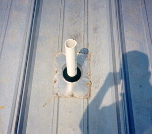
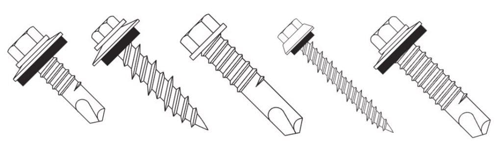
Coordination regarding material types of accessories, fasteners and placement is critical. There are materials that can react negatively with the installed system and lead to damage as well as void manufacturers warranties. Accessories should always be discussed prior to installation. Read more about different types of roof accessories and penetrations in MBCI’s blog article, Roof Penetrations Made By Non-Roofing Contractors.
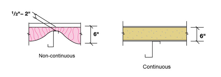
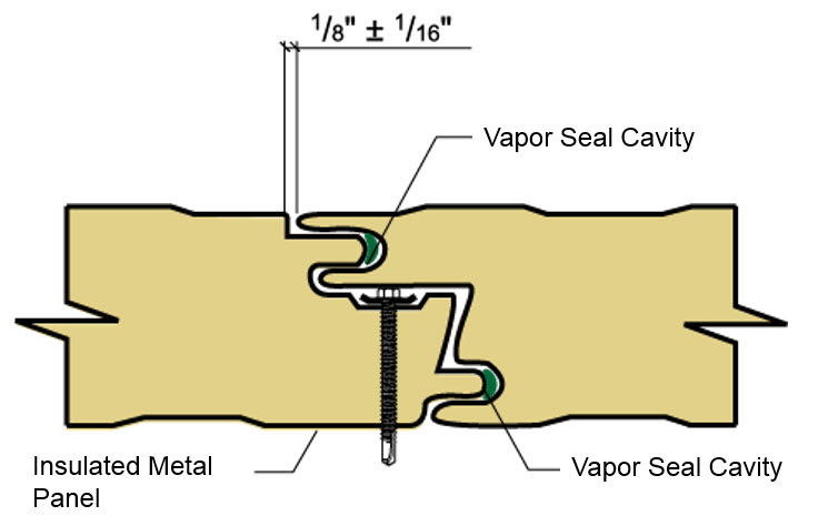
Panel Engagement

Panel systems have an engineered means by which the panels attach and engage one another as shown in the manufacturer’s installation manuals and project drawings. If at any point the panel will not engage as depicted in the details, installation should be halted and reviewed to determine the cause. This can require a call to the manufacturer to help determine if the matter is site and substrate related or potentially a manufacturing issue.

Do not continue to install the system if the laps are not nesting properly, clips are not engaging as detailed, panel modularity cannot be controlled or if the overall panel is not “resting” on the substrate such that there is excessive bowing and stress in the panel. This is the time to call the manufacturer, as once the material is completely installed, it is much more difficult to determine the cause of a problem and is potentially more expensive to remedy. Additionally, in many cases, full installation constitutes acceptance of the product and the manufacturer’s hands could be tied or extremely limited in being able to assist in remedying after the fact.

By knowing when to be proactive with a call to the manufacturer, installers can mitigate many types of potential pitfalls. And if you’re just not sure, it’s best to call.

For more information on metal roof and wall products and training, MBCI offers courses through its Metal Institute. These courses are available for general training purposes or for those seeking installer certification.

Knowing When to Call the Metal Manufacturer: Part 1

Metal panel installers have a tough job—not only navigating the details of the task at hand but also being confident enough to know when to seek the manufacturer’s guidance. Part of overseeing a successful project is for the installer to know when something is out of his or her comfort zone, beyond their expertise, or just doesn’t look or feel right. And when that’s the case, it’s imperative to call on the manufacturer for input before it’s too late.

Technical support, such as MBCI’s Ask the Technical Expert, can be most useful for answering upfront general product questions. Once the project has started or material is on the jobsite, it’s generally preferable for the installer to go through their sales person or field service/customer service representative rather than sending a question via a website.

When to Seek Assistance from the Manufacturer

First things first: The installer should study the installation manual and construction drawings. If, after that, he or she is experiencing a problem—for instance, the panel doesn’t look right, it’s not engaging properly, it’s not meeting the tolerances stated in the manual, the fasteners that are called out in the drawings are not working or are even missing—then contacting the manufacturer should be the next step. That one simple call can save a lot of time in potential headaches.

Improper Storage of Metal Panels
The above image depicts damage to metal panels caused by improper storage, rendering them unable to install properly.


While it’s not the manufacturer’s direct responsibility to make sure the installer is doing the job on site per the drawing details, a reputable manufacturer can at least provide recommendations when asked how to possibly alleviate or mitigate any number of potential pitfalls, or share common oversights that other installers have made—and how to avoid those same mistakes.

Top Circumstances

Here are two of the top circumstances under which MBCI recommends immediately reaching out to the manufacturer:

  1. Damage to the physical panel itself. If a customer receives materials and there’s suspected or noticeable damage to it, he or she may or may not know what impact that damage could initially have on the system. Notify the manufacturer immediately to assess if it’s a minor issue or if the panels should not be installed because it will be detrimental to the system. No one wants to have to reorder or wait for new materials, but it’s worse to wait until after installation when the impact of removing/replacing is significantly more costly and time-consuming.
  2. Fasteners. Contact the manufacturer if the substrate on site changes in any form from the project details, there is any difficulty with the screws themselves engaging, or any problems with the fastener type. When installing fasteners, make sure to use the ones per the installation details. The manufacturer can assist in verifying the correct fastener is being used in the correct location per the details and per the substrate on site. There could be situations where the installer is not accurately reading the drawing or has substituted an alternative screw not supplied by the manufacturer. Don’t assume. Instead, call.

There are, of course, other scenarios when a call to the manufacturer will save time, money and aggravation for all parties involved in an installation, including alignment and substrate issues, the addition of accessories, and problems with panel engagement. In Part 2 of this topic, we will go into more detail on these additional circumstances.

For more information on metal roof and wall products and training, MBCI offers courses through its Metal Institute. These courses are available for general training purposes or for those seeking installer certification.

Useful Tool: FM Wind Ratings RoofNav

The concept of testing materials and assemblies in buildings has been around since the late 1800s, when John R. Freeman initiated Factory Mutual Laboratories (now known as FM Approvals) to test fire protection systems. Since then, the use of FM-approved building components and assemblies has become recognized as an accepted safety standard for insurance companies, building inspectors, design professionals, and building owners. In the case of roofing systems, FM is particularly well known for determining how roofing performs not only for fire, but also for high wind. In fact, it is unique among other testing laboratories in the way that it performs wind uplift testing – it uses full-scale roof sections measuring 12 feet by 24 feet to obtain an accurate view of expected real-world performance. Further, it tests not only individual products, but full assemblies. In the case of metal roofing, for example, that would include the metal roofing panels, the fasteners (e.g., screws), EPDM washers, seam sealant, and any insulation, all as attached to a specific roof deck or structure.

Is it Approved by FM?

To find out if a roofing product or assembly has been approved by FM based on its independent testing, the best place to look is on the FM roof navigation website, known as RoofNav. Registration is free and offers access to FM’s fully searchable, comprehensive database.

How to Use FM RoofNav

Here is a quick overview on using the website:

  • My Projects Tab: The opening page is on the “My Projects” tab, which welcomes the user to RoofNav and lets a registered user save and return to specific data searches.
  • Product Search Tab: The second tab at the top of the web page is labeled “Product Search,” and allows a user to enter information under search criteria based on a manufacturing company and/or a trade name, as well as selectable roofing categories (such as “cover”) and subcategories (such as “composite panel cover”). Clicking on the “search result” sub-tab will show all of the corresponding products tested, and their approved uses. If a specific manufacturer, such as MBCI, is entered in the search criteria, the results will show only for that manufacturer. Clicking on a particular result will open detailed specifications and information for that product.
  • System Search Tab: If a particular system is being sought, such as a fastening system or vapor retarder system, the “search criteria” portion under this tab can help narrow things down by name, type, and products.
  • Assembly Search Tab: Since the real performance of a roof is based not on a single product or system, but an entire assembly, it is possible to search either by “classifications,” using basic criteria, or by “specifications,” which allow a detailed roof assembly to be created. Either method will produce a list of “search results” that can be clicked on to get more details. This is likely the most useful tab when looking to determine if a total roof assembly will meet the wind uplift rating needed for a particular project, but it does require that the proper details are input.

The website also contains a number of very helpful ways to assist a user. A tab for a “ratings calculator” allows flexibility in the amount of information entered; a tab for “reference materials” provides drop-down assistance with tools such as a “quick-start guide.” Links for “help,” “support,” and “training” appear at the top of the page, along with a quick-search portal where a known FM assembly number can be entered and found directly.

The RoofNav tool is a great resource for anyone who wants to find out test-result information about any one or a series of roofing products, systems, or assemblies, and can be a go-to resource for contractors, designers, and specifiers of roofing systems of all types.

Fire Resistance for Insulated Metal Panels

When it comes to understanding fire ratings for wall panels on buildings, one of the first things to overcome is incorrect information or misunderstanding that sometimes emerges around this topic. In an effort to achieve some greater clarity, let’s look at some of the basics of fire resistance ratings, particularly for insulated metal panels (IMPs).

Building Code Requirements

The fundamental reason that any wall needs to provide some degree of fire resistance is to allow people enough time to safely evacuate from a space or building in the event of a fire, or to prevent the spread of fire between defined areas or whole structures. Building and fire codes have been developed and adopted, in part, specifically to define the situations, building types, conditions and circumstances where different degrees of fire resistance are required to protect the public health, safety and welfare. Therefore, when looking at a specific building and the fire resistance ratings required, the applicable codes must be consulted and the proper determination made regarding the minimum fire resistance requirements for the different exterior and interior walls of that building.

Ratings-Based on Testing

The established means for knowing whether or not a wall meets a particular fire resistance rating is based on conducting a fire test in an independent laboratory. For IMPs, that means a manufacturer needs to submit full-size product samples to a laboratory such as Underwriter’s Laboratories (UL), which will then prepare and carry out the test according to standard, agreed-upon procedures such as ANSI/UL 263, “Standard for Fire Tests of Building Construction and Materials.” The procedures dictated by a standard such as this are intended to be the same for all similarly tested materials or products to determine the actual fire resistance rating for each. When the products are subjected to the prescribed heat and flame under uniform laboratory conditions, then they can be classified based on how well they performed. Some products, for example, may survive the test long enough to qualify for a 1- or 2-hour rating, while others may only qualify for a 30-minute rating before succumbing to the fire.

Urology Medical Office Building MBCI
The Urology Medical Office Building in Virginia Beach, Virginia utilizes 7.2 Insul-Rib® and CF Architectural – Horizontal insulated metal panels. View the product data sheets for these products for information on their fire resistance ratings.

Selecting Products

In creating or renovating a building, then, it is incumbent on the design and construction team to choose products and materials that have a proven, tested fire rating that meets or exceeds the building code requirements for the particular building at hand. If a manufacturer of IMPs has been identified ahead of time, then it may be possible to ask for evidence of the UL or similar test to prove that the selected product or assembly meets the code requirements. But many times, there is a need to first determine the requirements, and then look for the available products and manufacturers who can provide the needed fire resistance. Fortunately, UL maintains an online directory of all of the products that they have tested and certified. Their online certifications directory allows users to input selected criteria to search for specific result reports. Using this resource for IMPs, the UL Category Code of BXUV and the UL File Number of U050 should be entered to do a search. This will yield a summary list referencing the ANSU/UL263 test with a link to the BXUV.U050 test report for IMPs. There you will see under item 2: “Metal faced panels, nominal 42 in. wide by nominal 4 in. thick (for the 1 Hour Rating) nominal 7 in. thick (for the 2 Hour Rating) or nominal 8 in. thick (for the 3 hour rating) installed vertically or horizontally. Panels supplied factory double tongue and grove joint.” This lets the design and construction know that 1-, 2-, or 3-hour ratings are available depending on the thickness of the IMP and given that the factory joint is provided. Hence, the manufacturer can label their products accordingly.

By specifying and selecting the proper products that have been correctly tested and certified, then building code compliance is not only streamlined, the building will meet the inherent fire and safety requirements for the people who will occupy it.

For fire resistance information on MBCI panels, please review the product data sheets.

Combatting Thermal Bridging with Insulated Metal Panels

When using compressible insulation, say for instance fiberglass batt, consideration must be given to how that insulation is going to be deployed in the actual wall or roof. For instance, installers might place the insulation across the framing members and then smash it down with the cladding and run a screw through to the underlying structure. The problem here is that the insulation is rated with some R-value—and that R-value is determined by an ASTM procedure that also determines what its tested density is. So in essence, it’s ‘fluffy’ insulation.

One manufacturer’s insulation, however, might be thicker than another’s. The contractor is buying an R-value, not a density or a thickness. The insulation is tested to that R-value at whatever thickness and density¹ is needed to achieve it. Let’s say R-19 fiberglass batt is specified, but then it is put in an assembly and smashed down flat… now it’s not R-19 anymore; it’s now R-something else. That’s a thermal bridge—when the insulation’s R-value has been compromised.

Manufacturers have the ability to run long length panels that minimize the number of end joints. This continuity provides significant advantages over traditional insulated materials when designing for energy efficiency. This image illustrates the difference between fiberglass batting made discontinuous by compression between panel and framing members and the continuous insulation provided by insulated metal panels.

Unfortunately, thermal bridging is almost impossible to eliminate. In the example above, another choice might be to put it between studs. Except in this situation, the studs break the insulation. While it’s not pinched, the studs are separating it. Whether the studs are metal or wood, in either case it’s still a significant thermal short circuit or a thermal bridge.

Even with the highest quality insulation systems—insulated metal panels, for example—a joint is required. Building is not possible without putting neighboring panels together. Therefore, insulation is discontinuous. While it’s impossible to avoid thermal bridging, there are two requirements to ensure the building performs the way it needs to perform.

  1. Thermal bridging must be mitigated. In other words, the designer or installer has to try to eliminate as much of it as possible.
  2. If thermal bridging is unavoidable, it must be accounted for in some fashion, which usually means putting more insulation somewhere to make up the difference. This is called a “trade-off” and is allowed by most building energy efficiency codes.²

Why Insulated Metal Panels?

Insulated metal panels then are the best bet, because although the joint is a thermal bridge, in effect, it is not nearly as impactful as breaking a line of fiberglass with a stud or smashing the fiberglass between the panel and a framing member. In the illustration below, R-value doesn’t just vary at that point where the panel and the stud meet. The entire insulation line gets smashed and one would have to go some distance from the stud before the insulation returns to its normal, fluffy thickness. These issues need to be mitigated and accounted for.

assembled side joint
Continuous insulation is critically important to an efficient envelope design. Insulated metal panels, with their side laps designed for concealed fasteners, eliminate the possibility of gaps in the insulation and thermal bridges. Continuous insulation is important because thermal bridges and discontinuities introduced by compressing non-rigid insulations cause the in-place R-Value of the assembly to be less than the tested R-Value of the insulation used. This effect has become a focus in newer energy efficiency codes such as ASHRAE 90.1 and IECC.

Manufacturers such as MBCI and Metl-Span publish insulated metal panels as U-factors because the joint is tested as part of the assembly (both mitigating and accounting for the aforementioned issues). These values can be found on product data sheets and technical bulletins, such as Metl-Span’s Insulation Values technical bulletin, published January 2017.

References

  1. ASTM C 665 – 12, Standard Specification for Mineral-Fiber Blanket Thermal Insulation for Light Frame Construction and Manufactured Housing, Table 1, Footnote c.
  2. ASHRAE 90.1 – 13, Energy Standard for Buildings Except Low-Ride Residential Buildings, Section 5.6
  3. High Performance Green Building Products – INSMP2A (CEU)

Alignment Tolerances of Substrates for Metal Panels

Installers take note! It is your responsibility to ensure the substrate material over which you place the metal panels is in proper alignment before beginning installation. Otherwise, you can suffer some significant negative impacts on the overall appearance of the system.

As we’ve discussed in a previous blog article, Choosing Proper Substrates for Metal Roofing Systems, the substrate (or substructure) rests underneath the metal panels is a key part of the roofing or wall system. It serves two main functions: to act as a base to which the metal material is attached and to serve as a structural member to transfer loads to the primary framing system.

Knowledge is Power

Too many times, inexperienced metal building sheeting installers or sheeting-only contractors may not realize how big an impact alignment can have; it’s very easy to get too far into the process before recognizing there’s a problem. The issues must be dealt with at the very beginning of the process as well as the way through the installation of the panel system, whether it’s roof or wall panel installation, and must be checked frequently.

Major Misconception

One common misconception, especially for those new to the panel system, is that aesthetic anomalies are a result of panel quality. When troubleshooting, the manufacturer will ask a series of questions about the installation and alignment. However, by that stage, the installer may be beyond the point where it’s an easy fix, depending on the circumstances.

Key Considerations

  1. Understand the general panel installation characteristics by reading the installation manual. Become familiar with which screws and clips to use, and how the panels physically connect as well as types of insulation systems that work well with the panel system and if there are any limitations related to insulation types or thicknesses.
  2. Installers must be certain that the substrate material they’re installing over, whether metal or wood or something else, has been properly erected and properly aligned before panel installation begins.
  3. As they’re putting the panels over the substrate, installers should be checking the alignment, whether vertically/horizontally along the leading edge of the panel or inward and outward on the panel itself. With most metal panels, major variances in the substructure will cause the panel to accentuate any errors. As a result, the panels will look unattractive and be difficult to install.
  4. When the panel installation first begins, the installer might not immediately recognize there’s a problem. A variance in the steel or in the substructure can have a big impact, which won’t be known until it’s too late. As an example, consider erecting half a wall on a cloudy day without checking alignment. At the end of the day, it looks fine, but the next day when the sun is shining on it, the “aesthetic delights” due to misalignment are obvious.
  5. Check panels during installation for any damage due to handling, surface irregularities and how it engages or lays on the steel. Do not install any “suspect” panels and contact the manufacturer as needed.

Types of Problems with Alignment

  • Different types of panels can react differently to a substructure out of alignment. Some are more forgiving, and some are terribly unforgiving.
  • Overdriving fasteners combined with improper alignment is a killer 1-2 punch.
  • If alignment is not properly addressed/corrected prior, installers often try to push and pull the panel out of plane, resulting in “oil canning,” a common rippling effect that occurs with improper installation. It should be noted, this often is a direct result of the substrate and/or improper installation and does not have any bearing on performance, weather-tightness and warranty. It doesn’t look nice but is not a cause for rejection.
  • If the steel is out of alignment, the panels can be difficult to engage and perform the way they should.

What Can You Do?

Using a level, laser or a string line, an installer can measure/check the amount that the substructure is either going in or out of plane and correct as needed. For instance, the plane is zero mark-perfectly plumb, perfectly level. There’s an allowable tolerance that the substructure can be out of plane and still be acceptable. Manufacturers often publish recommended tolerances that should always be reviewed. The preferred tolerance being convex (outward) and never concave (inward).

Other Considerations

The main takeaway here is that steps should be taken to prepare a substructure to properly receive the metal panels. Then, diligently check as panels are being installed to ensure proper alignment is maintained and the installer is not inadvertently pushing and pulling them out of alignment, which could result in less than favorable final appearance.

Fastener Compatibility with Metal Roof and Wall Panels

The installation of a new metal roof or wall panel on a residential home, business or commercial building takes care, precision and—of course—the right tools. Regardless of the structure, you’ll likely find that choosing the correct mechanical fastener plays a key role in the long-term performance, durability and efficacy of the project.

Many metal roof and wall panels, in fact, rely upon the use of quality mechanical fasteners to secure components to a structure. In order to guarantee a resilient and weather-tight attachment, it behooves the user to select an appropriately compatible fastener type for the specific metal construction, thereby ensuring expected benefits, such as energy efficiency, extended life cycle, and even lowering insurance bills for the owner. In other words, once the decision has been made to use metal building materials for your roof or wall project, the next step is figuring out how to hold it all together.

Know Your Fastener Options

Before selecting fasteners for the project, it is important for the designer or installer to understand the various materials and options available. Typically, this involves the following considerations:

  • What type of material and coating is appropriate?
  • What type of head do I need? Does it need to be painted?
  • Do I need a washer? If so, what material should I use?
  • Should I use self-tapping or self-drilling screws?
  • What thread count should I specify?
  • How long does the fastener need to be?
Many Types of Fasteners
The MCA provides a summary of the different types of fasteners in their technical bulletin, Fastener Compatibility with Profiled Metal Roof and Wall Panels.

Select a Fastener on the Basis of Material

Most fasteners are made from coated metal but both the type of metal and coating must be chosen on the basis of the materials the fastener is bringing together. Galvanic action between dissimilar metals can cause premature fastener failure and lead to leakage. Even stainless steel screws will corrode severely under the right (or actually wrong) conditions. In extreme exposure, sometimes the best option is to use galvanized screws and plan on replacing them at a later date with a larger screw once the zinc has been depleted.

Considerations for Self-Drilling Screws

Self-drilling screws have a drill bit built in and don’t require a pre-drilled hole. Although self-drillers save the installer the step of drilling a hole, they are not always a good idea. The available space between the back of the hole and the next physical restriction must be at least as big as the bit itself or the threads will not engage. Also, drilling a hole allows a quick inspection to ensure the hole is in the correct location and plies are aligned and parallel. Generally, self-drillers are used when going through thin gauge steel into thicker gauge steel and self-tappers are used when fastening two thin gauge plies.

Washers

Fasteners may be used with or without washers. While plastic washers help prevent leaks, they are not required on purely structural connections. When using washers, it is important to visually inspect the screw after installation to be sure they are properly compressed and not kinked. Exposed plastics generally degrade when exposed to ultraviolet light. Furthermore, use of neoprene washers may be prevented by restricted material lists, or “red lists.” Fastener heads themselves may be made of different materials than the rest of the screw, long-life ZAC heads being the most common example.

Fastener Profiles

Fasteners have different profiles. Flat or “pancake” screws are used when low profile installation is necessary and may have Philips, hex, or Torx sockets. Which socket to use is usually an installer’s preference based on accessibility restrictions. Another common feature is an over-sized dome beneath the head to encompass a larger washer. Also called shoulder screws, these screws are useful when thermal movement might distort the holes.

Colored Fasteners for Metal Roofs
Fasteners can also be colored to match the roof or wall panel.

Thread Count per Inch

Thread count per inch, or TPI, must also be considered. Most commonly, fasteners are installed through the thinner ply first and grip in the thicker ply, pulling the plies together. Therefore, TPI selection is usually driven by the thickness of the thicker ply. Generally, the TPI is close to the gauge of the metal for gauge steel and higher for plate and sheet.

Length

The fastener must also be long enough to fully engage all plies of material, plus the length of the drill bit in the case of self-drillers. Generally, this is rounded up to the next half or quarter inch. However, the longer the screw, the more torsional strain is produced during driving and in the case of very long fasteners, this can break the fastener or introduce wobble, leading to poor installation. Therefore, stainless steel with over-sized washers is often used for long screws for added strength and protection.

For More Information on Fastener Compatibility

To learn more about fasteners and their compatibility with different types of metal roof or wall panels, check out Metal Construction Association’s recently published technical bulletin, Fastener Compatibility with Profiled Metal Roof and Wall Panels.

The Benefits of Integrating Daylighting Systems with Metal Panels

When metal roofing and wall systems of insulated metal panels, or IMPs, are combined with integrated daylighting and electrical lighting systems (such as with skylights, windows and translucent panels) it can improve occupant wellness and overall building performance. Are you curious if the return would be worth your investment? Uncover the recent advancements in daylighting technologies, the benefits and how to measure your building’s success.

Advancements in Daylighting Technologies and IMPs

In recent years, IMP assemblies have seen significant improvements, including more effective seals and thermal breaks as well as better thermal performance.

A range of novel daylighting products and technologies have been introduced in recent years that aid in the deployment of natural illumination for a multitude of occupancies—maximizing daylighting effectiveness while also maintaining the envelope’s barrier and thermal performance. These tools include pre-engineered, integrated metal envelope and roof solutions with compatible curbless skylights, light tubes, pan-type prismatic skylights, automated dimming controls for lighting, motorized shades and other components.

One example of how new tools are replacing more traditional products is the use of domed and pan-type units with prismatic embossing, which refracts and directs two to four times as much illumination into the indoor spaces when solar incidence angles are more acute, such as in the early morning and late in the day. These prismatic elements also help eliminate “hot spots” and reduce glare and ultraviolet (UV) deterioration from daylighting.

Daylighting with Metal Roofing

Benefits of Investing in Daylighting

Overall, using the current crop of novel skylight products in combination with a highly thermally efficient base system of metal panel walls and roofing will reduce excessive solar heat gain as they reduce the electrical base load for lighting. Highly diffusing acrylic and polycarbonate lenses and spectrally selective glass openings are very effective for maximizing functional visible light indoors while inhibiting unwanted heat gain. Many of the skylight aperture designs block 85% of infrared (IR) and 99.9% of UV light, which also reduces the unwanted degradation of products and materials inside the buildings. Additionally, the new generation of skylights also optimizes solar harvesting because many of the lenses have a minimal effect on VT.

In this way, the use of skylights with metal roofing and IMPs can be an effective way to meet the requirements of IECC 2012 and state energy codes. The skylights reduce overall electrical loads without adding unacceptable levels of solar heat gain, and their small relative area means the overall roof U-values remain low.

How to Measure the Success of Daylighting

Building teams will encounter a number of key variables that help measure the effectiveness of proposed daylighting designs. The most common (and valuable) daylighting performance metrics in use today include the following:

• Daylight factor
• Window-to-wall ratio, or WWR
• Effective aperture, or ea.
• Daylighting depth
• Solar heat-gain coefficient, or ShgC
• Haze factor
• U-factor

Using the above tools and terminology, building teams can better assess the benefits of daylighting strategies with skylights, prismatic pan-type products and solar light pipes, among others. In particular, these are important for meeting the widely used 2012 International Energy Conservation Codes (IECC) and ASHRAE 90.1 as well as state energy codes and “reach targets” such as green building certifications, the Passive House standard and others.

How to Learn More

The use of building systems combining metal roofing with skylights and integrated lighting provide significant life-cycle performance. Much of this is due to the research and development behind the individual products and materials used for these applications.

For a more in-depth look at daylighting within the context of metal roof and wall systems, please refer to MBCI’s whitepaper, Shining Light on Daylighting with Metal Roofs, which showcases the strong rates of return of using integrated daylighting systems with novel prismatic optics and high-efficiency lighting on metal envelopes with good thermal and barrier performance.

Download the White Paper, Daylighting with Metal Roofs

Daylighting 101

In the age of increased energy efficiency requirements in buildings, designers often find themselves spending time and resources squeezing performance out of systems with relatively little gain in efficiency. More and more, building insulation systems seem to fall into this category. The authors of the building codes recognize this as well and have reacted by turning their focus on other metrics like air infiltration where more substantial gains are to be had. A similar situation exists with lighting efficiency. However, when it comes to daylighting, designers are often pushed out of their comfort zone because lighting concepts and terminology is quite esoteric and difficult to comprehend.

Daylighting
m
The truth is that most people take light for granted and aren’t aware of the complexity of lighting for human activity and comfort. Probably the biggest reason for this complexity is the fact that the human eye is the only way we can judge light and although the eye is an evolutionary masterpiece, it has its own idiosyncrasies and no two eyes work identically. For instance, the typical human eye can discern shades of green at much greater accuracy than other colors and because of this sensitivity, green light is often perceived as brighter than other colors at the same energy level. Therefore, quantifying light level for human comfort and function must take this sensitivity into account, leading to some complexity. Here are some basic principles that you need to understand:

A steradian is a unit of solid angle measure. You can think of a 1 steradian solid angle as a cone cut out of a sphere with the apex of the cone at the center of the sphere and cross-section angle of approximately 66 degrees. A unique property of a 1 steradian solid angle is that the area of the semispherical “cap” captured by the cone is equal to the radius of the sphere squared. This makes it a convenient shape to use in measuring the amount of light projecting from a source at the apex of the cone through its interior and onto the cap because the amount of energy passing through any cross-section along the way is always the same. There are 4π, or approximately 12, steradian in a sphere.

Surface area of the "cap" is equal to radius of the sphere squared.

Light is generated at the molecular level by the outer bands of electrons surrounding a given atom. When these electrons become excited at a high enough level, they emit a burst of energy in the form of electromagnetic radiation of a wavelength interval unique to the emitting atom in order to return to a lower energy state. If the energy level is just right, this wavelength will be in the visible light spectrum and viewed as a specific color. White light is formed when many atoms respond at various energy levels distributed across the entire visible spectrum in a pattern such that the energy transmitted is roughly constant with wavelength. The human eye is not responsive enough to discern the different colors hitting it, so an overall stimulation results in a static or “white” response. (There is a similar concept for sound as well, called “white noise”, when the ear cannot detect the individual vibration frequencies.)

The absolute brightness of light is given by the total energy it transfers through electromagnetic modulation. It is determined by summing up the energies transferred by each incorporated wavelength. As light travels from a point source, this energy spreads, causing the amount of energy arriving at a single point in space to decrease as that point is placed farther away from the light source. Brightness decreases with the square of the distance from which it is viewed. In other words, a light will appear ¼ as bright when viewed from a distance twice as far.

Because the human eye is more sensitive to green light than other colors, the brightness it perceives from different lights can only be effectively compared at the same color or wavelength. For light used for human function and comfort, it has been standardized to quantify the brightness at the 555 nanometer wavelength, which is near the center of green in the visible light spectrum, and then adjust for the effect of other colors consistent with how the human eye perceives them. Color is accounted for by weighting the energies transmitted at other wavelengths using the luminosity function. The resulting quantity is called perceived brightness. The luminosity function is similar to a bell curve and it represents how relative brightness of various colors is perceived by the typical human eye. As you might expect, the luminosity curve peaks at a wavelength near 555 nanometers.

Absolute brightness is measured in watts and should only be used when comparing lights of the same color. This should not be confused with power consumption, which is also measured in watts. Perceived brightness is instead expressed in candela and is the only way light of mixed color (on non-monochromatic) can be compared. A one candela light source with a wavelength of 555 nanometers transmits 1/683 of a watt of energy.

It is also important to be able to quantify total light output of a light source. Real-world light sources are not usually of equal brightness in all directions, so candela is not the best measurement to use. To account for spatial variation, total light output is defined as the sum total of light passing through every point in a cross-section of a one steradian solid angle, considering a light source at the apex, divided by the area of the section. This results in the same quantity regardless of the location of the cross-section. So, if a light were to transmit one candela through each point in the cross-section of a unit steradian, then it would be said to produce one lumen of light. Likewise, a 555 nanometer light source radiating one watt per steradian of energy produces 683 lumens.

Finally, the effect of light projected onto a surface must be defined, commonly called illumination level. If a light projects through a solid angle of one steradian at a uniform perceived brightness of one candela, the illumination level achieved one foot away is called a footcandle. This definition confuses many people because it is contrary to what the name might imply. But because a unit steradian is used as the basis, a footcandle equates to one lumen per square foot and it is generally much easier to think of illumination level in this way. Lux is the metric equivalent to a footcandle and there is about 10.8 lux in a footcandle. Since illumination level differences of one tenth of a footcandle are not detectable by the human eye, this is often simplified to 10 lux per footcandle.

To put this all into context, a dome skylight 24” in diameter, elevated a foot above a 30’ high roof on a 20’ x 20’ grid on an open building in El Paso, Texas, achieves about 25 footcandles at a level 4’ above the floor at noon on March 21st (typical spring equinox). Compare this versus the following recommended illumination levels for various tasks as recommended by The Whole Building Design Guide:

Whole Building Design Guide Illuminatin Levels

Understanding these concepts will help you get more out of MBCI’s latest whitepaper, Shining Light on Daylighting with Metal Roofs, where MBCI explores the subject in detail, wholly within the context of metal roofs and metal wall systems. We hope you find it…err, enlightening.

Download the White Paper, Daylighting with Metal Roofs

Part III – Transparency Plus Consensus: A Win-Win for Everyone

Part III transparency plus consensusIt has been a long time since my last blog on this subject. This is not only because I’ve been busy but also because the landscape of green building programs in general has changed significantly since Part II, and I wanted to wait to see how things shook out before I wrote something that might be immediately outdated. If you remember, we left off in Part II talking about how LEED, the most popular green building program in the US, has not been developed through an ANSI accredited consensus process. Furthermore, the resulting lack of transparency was dubiously ironic given that LEED demands a high level of transparency from building product manufacturers min the latest version of their program, LEED v4.

We also discussed the related but more general movement for manufacturers to fully disclose all of the ingredients in their products to a third party who then compares that list to lists of known hazardous substances and disclose any matches on a product label or public disclosure for all to see. This movement has been fueled by several large architecture firms sending letters to building product manufacturers threatening to stop specifying their products unless they participate. Although most manufactures agree that there is merit to disclosure and are anxious to participate in a fair program, they have not been privy to discussions regarding the logistics of such a program nor have they been allowed to participate in any kind of a standard development governing the disclosure process. This makes manufacturers reluctant to participate, given their vulnerability in such a situation. This risk is leveraged by the fact that currently the only standards that dictate the rules of such a program are under the control of consortiums who have little to no scientific expertise and, frankly, have not been friendly to the building products industry in the past.

I also mentioned that there are alternative programs to LEED that have been developed through a valid consensus process. Specifically, the International Green Construction Code (IgCC), ASHRAE 189.1 and Green Building Assessment Protocol for Commercial Buildings (also known as Green Globes) are ANSI standards that outline the relevant requirements for anyone to view. However, the USGBC marketing machine and resulting popularity of LEED prevented wide use of these standards. Thus, they remained largely unutilized. That is until this year, when the USGBC, IgCC and ASHRAE signed a Memorandum of Understanding, promising to work together and create a favorable consensus by eliminating duplication of provisions and assigning an area of responsibility for each group to maintain separately.

Although no documents have yet to be created, it appears that the administration and enforcement provisions of the new standard will come from the IgCC, and the technical content will come from ASHRAE 189.1, both of which are consensus based. Meanwhile, LEED will require compliance with 189.1 as a prerequisite to an upcoming interim version of LEED. This approach allows an Authority Having Jurisdiction (AHJ) to adopt the IgCC as a minimum standard of construction; dropping any reference to LEED they might currently have as minimum project requirements for all buildings. This leaves LEED to evolve as a completely voluntary program going forward and push the envelope of green building, which is their core mission. Meanwhile, Green Globes remains ANSI accredited and still exists as a commercial competitor to LEED. This environment should result in a more user friendly application process, the lack of which been a ubiquitous criticism of LEED for years, because Green Globes is much more user-oriented.

So, it appears that the most popular green building programs are poised to move in the
direction of a true consensus, which is fantastic news for everyone involved. However, the creation and development of disclosure programs, which will not be in the initial technical requirements provided by ASHRAE 189.1, remains largely a one-sided affair with no seat for manufacturers at the table. Besides the contentious nature of the subject in general, there are major philosophical questions that have to be addressed before Health Product Declarations (HPDs), or any type of disclosure in general, can be brought into the main stream. That subject is beyond the scope of this blog, but I encourage you to read a very good article on the trappings of HPDs called “Disclosure: The Newest Dimension of Green Building” by Jim Hoff.

The good news is that there may be a viable alternative to HPDs on the horizon. ASTM has a current open work item to develop a true consensus based standard guiding the issuance of a Product Transparency Declaration (PTD), which has much the same intent as an HPD. As discussed in Part I, the development of ASTM standards is a highly transparent process that allows everyone, including manufacturers, to come to the table. I encourage every designer to join ASTM and get involved in this process, especially those firms who participated in the letter writing campaign, and forgo HPDs until PTDs are available.

Yes, it will take a little longer; the reality that the development of consensus based standards takes time. But just like the development of the laws that govern this country, there is far too much risk involved in getting it wrong. Instead, having these standards developed by a consensus-based process is the only way the finished product will be truly useful and meaningful.

Find a sales representative