In a prior post on insulated metal panels (IMPs) we reviewed some of the basic things everyone should know about this versatile and lightweight metal building component. In this posting, we will drill down a bit more on the benefits of incorporating IMPs into a new or retrofit construction project. Here are some of the top reasons they are so popularly used in both walls and roofs:
Insulated metal panels (IMPs) are a popular choice for walls and roofs for their energy conservation, durability, longevity and cost-savings.
Energy Conserving, Space Saving Insulation
Foam plastic insulation is used between the metal skins of IMPs. Such insulation has been accepted for use by building codes for quite awhile provided it meets certain conditions. IMPs have been tested and shown to meet or exceed all code requirements for construction and for energy conservation too. Part of their appeal over other ways to insulate is that they can achieve high performance in a thinner wall or roof assembly than would be required with other types of insulation, such as fiberglass. IMPs are available in thicknesses that range from 2 to 6 inches and have corresponding R-values from R-14 to R-46 allowing design professionals to select the thickness that matches the energy performance level sought in a particular building. Other insulation types would require thicknesses of at least twice as much to approach the same R-values as IMPs. Further, the metal interior and exterior skins are the only finish material needed so the total panel thickness is very space efficient. Thinner IMPs in the walls and roofs can save space in the building or on the site all while achieving high energy performance.
Durability, Longevity, and Low Maintenance
The manufactured panels are rigid and quite strong. They have been tested for compression, tensile, and shear strength with impressive numbers that come about because of the combination of the rigid foam and steel properties. The surfaces are made from the same long-lasting galvanized and factory finished steel used in other metal wall and roof panels so their resistance to weather, abuse, and even harsh conditions has been proven, making them very easy to maintain. In locations where severe weather and storms are a concern, they can also be specified to meet requirements for heavy winds, hail, and similar concerns. Plus, since the skins of the IMPs are made of noncombustible steel, they provide an ignition barrier as part of an overall fire protection scheme for the building.
Cost Saving Construction
IMPs are an “all-in-one” product that takes the place of many other products and components used in traditional construction. Instead of requiring multiple trades and materials to be installed individually over some number of weeks, IMPs are installed by a metal building contractor and allow the walls and roof to be completely closed in with a single trade. The use of concealed fasteners in the side joint of the panels makes installation quick and easy. Unlike other construction systems, the inherent strength and resiliency of IMPs means that work doesn’t need to stop over weather concerns. All of this saves a considerable amount of labor costs and can also save a lot of time meaning buildings can be completed quicker and more economically. It could also mean that an owner is able to occupy and use the building sooner, thus reducing construction financing costs and allowing operations to begin more quickly.
Versatility for Use in Many Building Types
IMPs can be used in virtually any type of new construction and for many retrofit applications too. There is a range of modular panel sizes that can work successfully with different structural elements of the rest of the building. The finished profiles and colors can all be selected to match the design needs of the building with edges, corners, and trim details all based on simple, appealing aesthetics. There are even IMPs specially designed for cold storage or refrigerated space applications. These panels may be part of the building exterior or create an isolated space within a larger building. Either way, they are designed for the rigors of a high use installation.
With such a broad range of benefits and capabilities, you owe it to yourself to check them out for a building project that you may be involved in. The best place to start is by contacting your local MBCI representative, and by signing up for our newsletter to subscribe to our blog.
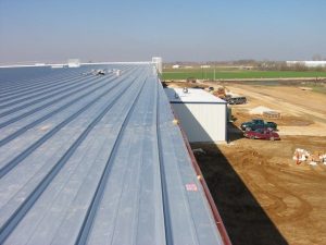
Standing seam roof (SSR) systems are built to move, designed to account for necessary—and often substantial—expansion and contraction due to thermal conditions. In fact, for many builders, this fact is one of the main reasons SSRs are such an attractive option.
Even with this expectation baked into the mix, many contractors and installers may still make a wrong turn when tying the SSR into adjacent structures and other building edge conditions. By not allowing for that same expansion and contraction on trims and transitions, problems can ensue.
Fixed and Floating Clips
One main consideration in planning for this movement is the clip type used. Standing seam metal panel clips are designed specifically to interact with their corresponding roof panels in order to allow movement (both interior and exterior) caused by thermal changes. The clips, which are part of the concealed fastening system used with SSRs, provide improved aesthetics in addition to durability and protection from the elements.
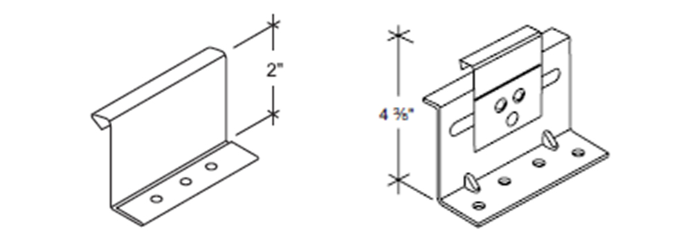
Fixed Clip (left) Floating / Sliding Clip (right)
The two main options are fixed clips (one-piece) and floating/sliding clips (two-piece). Fixed clips are limited by and dependent on the substrate’s ability to expand and contract with the roof system, whereas floating/sliding clips permit the panels to expand and contract within the clip itself. These clips will allow for greater thermal movement of the panel, which is independent of the substrate while still ensuring the panel remains secured. Regardless of which clip is utilized, you are not going to stop the expansion and contraction. You can, however, have some control of the direction of movement, and, therefore, can address or compensate for the degree of this movement when tied into adjacent structures.
While standing seam roofs are designed for movement, correctly tying it to the rest of the structure is crucial.
Standing seam roofs with floating/sliding clips require one end of the panel run to be “pinned” and the other end to be “moveable” in order to permit expansion and contraction. The “pinned” point of the system is typically the low eave, although it doesn’t have to be. There will be instances when it becomes beneficial to “pin” the roof at the complicated transition or tie-in point and design the roof system to expand/contract outward from this location. This can eliminate potentially “troublesome” areas from the equation on having to deal with the roof movement, and in turn can make them easier to install and have greater weathertightness success.
With all this in mind, it is important to always check with the manufacturer to determine the best clip and design layout to use with any given SSR system and be aware of how much and in what direction the expansion and contraction is going to occur.
Tying In
Not only does the building move, but anything it ties into has to be able to permit that movement, e.g., the edges or perimeter of the buildings. Manufacturers can provide both longitudinal and transverse transitions that allow for thermal movement so that when they tie into an adjacent structure it doesn’t restrict the panel from moving. Not adequately compensating for or preventing that movement entirely can lead to potential pitfalls, such as oil canning. It could also lead to fasteners backing out and slotting of holes. Bottom line, any time that we try to confine or restrict the roof from doing what it was meant to do (move!), we inevitably run the risk of damaging the panel not just aesthetically but more importantly, from a weathertightness standpoint.
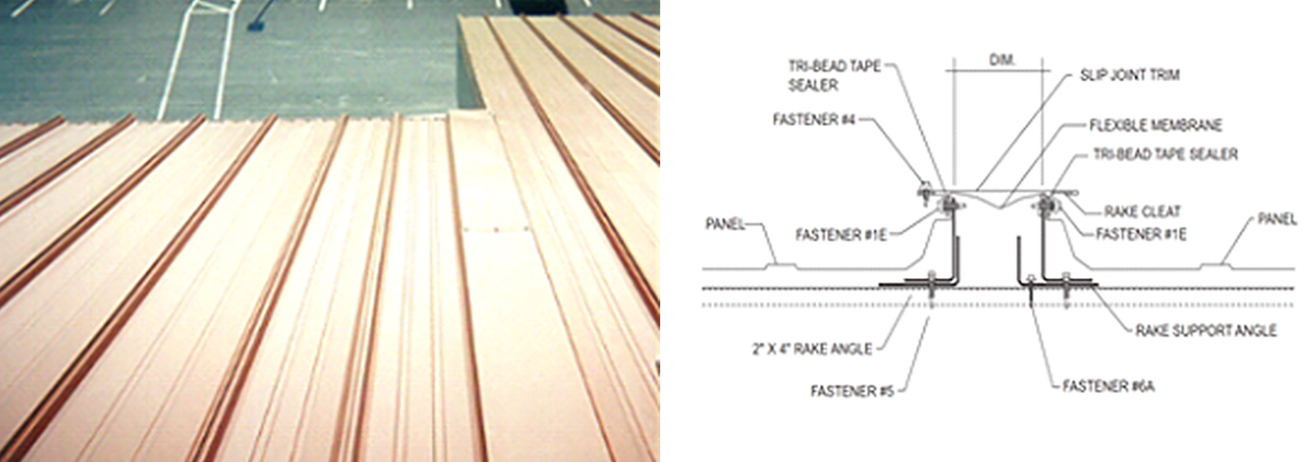
Slip joint being used for transverse tie-in between adjacent roof surfaces.
The Role of Expansion
Issues can arise not just when tying panels into adjacent structures. Because of the roof’s size and magnitude of potential movement, you may/will have to implement expansion/contraction capability of various degrees into the perimeter of the roofing system itself. In these cases, this is why manufacturers offer roof accessories as ridge expansions, edge trim expansions, panel expansions, gutter expansions and other details to account for not only the roof movement but the perimeter trims that are secured from the roof system to the wall system.
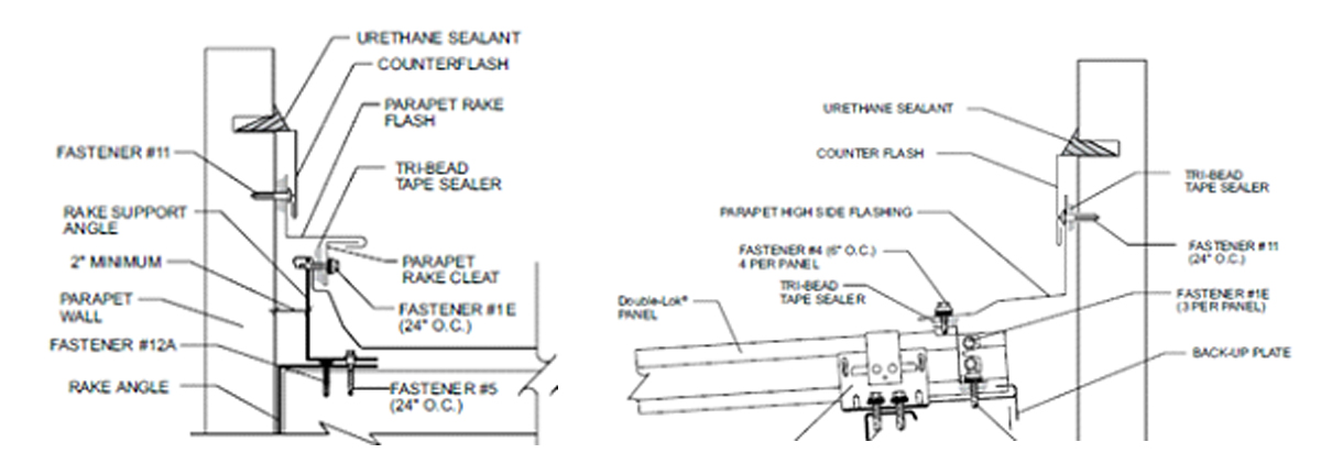
Parallel Roof Transition (left) and Perpendicular Roof Transition (right)
Know Your Details
The key takeaway here is to remember that if you’re considering a standing seam roof for a project, then you need to make sure that the designer looks at every detail from the manufacturer and accounts for movement of the roof panel, such as how it ties into adjacent structures or simply how the edge or perimeter of the building is terminating to make sure they permit that expansion and contraction. Know what you’re buying and understand that if the roof you’re purchasing is meant to expand and contract, everything that ties into it has to be able to expand and contract as well.
To find out more about how to correctly install your standing seam roof, contact your local MBCI representative.
Insulated metal panels (IMPs) are “lightweight, composite exterior wall and roof panels with metal skins and an insulating foam core” as defined by the Metal Construction Association (MCA). The outer skin serves as either metal wall siding or metal roofing using standard profiles, while the inner face serves as a metal interior finish or liner. The rigid insulation between the metal skins gives the panels their superior energy conservation properties and also provides a rigid core for extensive spanning capabilities across structural members.
With this basic make-up in mind, here are a few things you should know about using IMPs in a metal building project:
Building Types
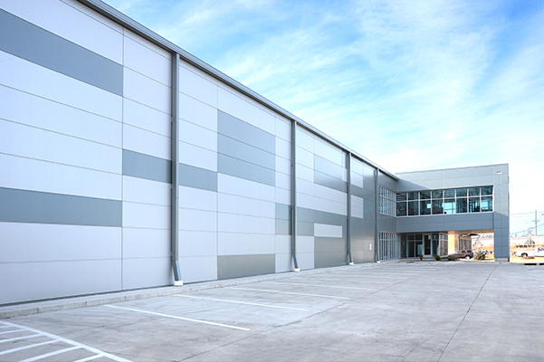
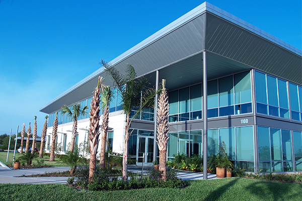
Virtually any building being designed as a metal building should consider the use of IMPs. This includes all types of commercial, industrial, institutional, recreational and government buildings. More specifically, IMPs have been used very successfully on manufacturing facilities, schools, retail centers, offices, warehouses, power plants and many other building types.
Insulated Roofing and Walls Assemblies
IMPs serve as a complete wall or roof assembly. That means they can provide cladding, insulation, a water-resistant barrier, an air barrier, and finished surfaces all in one panelized product – essentially everything but the building structure upon which they are installed. These characteristics are true for conventional buildings as well as for specialty construction types such as the climate controlled processing, storage, or distribution of perishable food or other items. With panel thicknesses commonly available from 3 inches to 6 inches, walls and roofs can be designed to meet the specific thermal performance requirements of virtually any building need.
Aside from their thermal performance capabilities, IMPs have the versatility to achieve countless aesthetics for walls and roofs.
Architectural Design
IMPs are available in a wide variety of colors, widths, profiles and finishes, enabling virtually any aesthetic desired for walls and roofs. Further, architectural IMPs provide the freedom to address building-specific or unique circumstances with options such as custom shapes and widths, special custom colors and finishes, custom fabrication including, but not limited to bent corners, curved panels, and trimless ends. Architectural IMPs also offer options to integrate with windows, louvers, sunshades or other similar products to offer total building envelope solutions.
Panel Joints
Most IMPs are fabricated with the intention of working together as a complete system. That means attention has been paid to the design of the edges so the panels can interlock and be sealed to form a continuous joint that is water tight and air tight. In some cases panels may need to overlap, such as on long roof runs over 50 feet, but manufacturers have worked out those details to help assure the roof or wall performs as intended. Based on this, properly-installed IMP systems generally come with a very long warranty period.
Ease of Installation
The fact that IMPs are a single, finished, rigid panel, makes them quicker to install than other multi-product and multi-step assemblies. This translates to obvious labor savings and some material cost savings compared to other systems. Further, the simplified installation process has been shown to limit exposure to accidents, helping create a safer, more efficient work flow. It can also mean that construction time schedules are easier to meet or even beat.
To find out more about IMPs and ways to use their full characteristics and capabilities on a building you are working on, contact your local MBCI representative.
The primary purpose of a building’s envelope (roof and walls) is to protect the building’s interior spaces from the exterior environment and provide the desired exterior aesthetics. Whether choosing insulated metal panels (IMPs) for their superior performance or, instead, looking to the wide range of aesthetic choices available with single-skin panels—or some combination of the two—the common goal must always be to protect the building from the potential ravages of water, air, vapor, and thermal/heat. By ensuring proper installation of metal panels and, thereby, properly sealing the building envelope, problems can be mitigated, efficiencies maximized, and the integrity of the building protected.
Here, we’ll briefly consider the benefits of each panel, and some key considerations relative to their sealant needs and capabilities.
Insulated Metal Panels (IMPs)
IMPs are lightweight, composite exterior wall and roof panels that have metal skins and an insulating foam core. They have superior insulating properties, excellent spanning capabilities, and shorter installation time and cost savings due to the all-in-one insulation and cladding. In effect, IMPs serve as an all-in-one air and water barrier, and are an excellent option for retrofits and new construction. With their continuous insulation, roof and wall IMPs provide performance and durability, as well as many aesthetic benefits.
IMPs offer excellent R-value and improve energy efficiency to the building envelope.
Generally speaking, because of the nature of the joinery, it is easier to get a good seal in place with IMPs given their relative simplicity (i.e., putting the two pieces together with the sealant). They require great attention, though, in terms of air and vapor sealing—aspects largely controlled by the installers on a given project. As an example, vapor sealing in cold climates or applications is critical to the overall soundness of a building. Consider the damage a building could incur if moisture seeps into a panel and becomes trapped; it if freezes, it could push panels out of alignment. This would result in not just an unattractive aesthetic, but a performance failure as well. In order to be effective, all sealant and caulking must be fully continuous.
Single-Skin Panels
Single-skin panels, alternatively, offer the advantage of an expansive array of colors, textures and profiles. They are also thought to have more “sophisticated” aesthetics than IMPs. Single-skin panels are available in both concealed fastener and exposed fastener varieties, and are part of an assembly. They can be used alone or in combination with IMPs, and as long as the needed insulation is incorporated, single-skin panels can meet technical and code requirements, depending on the application. Single-skin products offer a wide range of metal roof systems and wall systems as well.
Getting the proper seal on single-skin panels may require extra sealants or closures, and have more parts and pieces that have to come together to create the seal. However, when properly installed and sealed, they can provide excellent performance in their own right. Some key caveats include ensuring panel laps are properly sealed with either tape or gun butyl sealants, and carefully inspecting air and water barriers for proper installation as well as penetrations through the wall for sealing/fire caulking prior to panel.
In most cases, following the details for the most common conditions will give you a successful and high-performing outcome.
Regardless of the type of metal panel used, taking the time and effort to ensure the sealing and caulking details are properly handled, metal buildings can protect the built environment and provide long-lasting quality and performance.
Energy codes and increasing energy costs have prompted the installation of more roof insulation into metal buildings in recent years to make them more energy efficient. That is fundamentally a good thing and metal building manufacturers have developed ways to accommodate a variety of building enclosure packages that increase energy performance while still being engineered to meet the structural requirements of the building. This allows the whole building envelope to be designed and fabricated so it works as a complete, coordinated system.
Insulation helps maintain a comfortable interior temperature in your metal building during the winter and summer months.
The metal roofing or metal building suppliers typically don’t design the insulation systems. However, it is important to include them in the discussions or make them aware of what type of system is to be installed. It is not uncommon for a metal building to be ordered with the design stipulation of “insulation by others.” In that case, coordination is needed between the person ordering/designing the insulation system and the metal building manufacturer or roofing supplier. Since there are a great many variables in the way that insulation can be provided, it is not appropriate to think that the design of structural systems (purlins and roof bracing) and cladding systems (clips, fasteners, and metal roofing profiles) will necessarily accommodate all the same insulation in all conditions. Rather, unless the specific details of the insulation system being used in the building are communicated effectively at the time of the order, the manufacturer can not assure compatibility of the systems used with the insulation system that is to be installed.
In order to understand some of the variability in the options, let’s look at some of the common ways that metal buildings are or are not insulated.
Uninsulated Roofs:
Buildings that do not have any heat or air conditioning in them may not need for an insulated roof. This could be true for outdoor shelters, some agricultural buildings, or vehicle storage buildings. However, uninsulated metal roofs have the potential for “roof rumble” as they move due to thermal expansion and contraction, wind, or weather as there is no insulation to mask or deaden this noise. Absence of insulation can also lead to condensation during certain times of the year if temporary heat is added to the building. This condensation builds up and can drop or fall onto whatever is below. Many times condensation issues are mistaken for roof leaks when in fact it’s a mechanical design issue of the building envelope that’s not been properly addressed. If neither sound nor potential condensation are a concern, then there’s no problem. But if either or both need to be avoided, then some basic level of insulation may be prudent.
Over the Purlin Systems:
One of the most common insulation systems for metal buildings and/or open framing systems is to simply install rolls of blanket insulation. In this case, fiberglass insulation with a reinforced liner is draped over structural beams and purlins. The rolls are supplied to length by the insulation supplier based upon the roof structural layout and the required “R” value necessary for the building envelope in thicknesses that can vary from 3″ to 12″. Is is this thickness to be installed over open framing that the metal building/roofing supplier must be made aware of. Based on this thickness, the panel profile can be verified to determine if it can be used as well as confirmation of the correct clip heights and screw lengths for installation. Keep in mind that the supplier will offer a guide to the installer based upon insulation thickness. As insulation can vary by manufacturer, it will be up to the installer to make adjustments as needed in the field to ensure proper placement and hold modularity of the steel system. (See Respect the Module: Metal Roofing Panels are Modular for Good Reason)
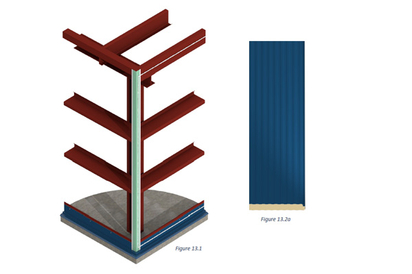
Cavity Fill Insulation Systems:
When higher “R” values are required for roof insulation, a single layer over the open framing system may not be sufficient. When that occurs, the designers of the building envelope may need to employ the framing cavity to add more insulation. There are also variation on the cavity fill approach.
One means is to simply introduce a second layer of unfaced blanket on top of the faced insulation. Sometimes referred to as a “sag and bag” approach, here the first layer of insulation over the purlins is ordered to accommodate larger amounts of drape between the roof structure to permit another layer of unfaced insulation to be added on top. This increases the insulation thickness between the purlins but keeps it thin enough to be compressed to accommodate the roof panel installation. For coordination purposes, the thickness of this upper insulation over the purlins needs to be known by the building manufacturer so the clips and fasteners can be properly sized. Likewise, the amount of insulation draping between the purlins needs to be known to determine if purling bracing or other accessories may potentially interfere with the insulation installation.
Other types of cavity fill system may include a faced batt or face roll insulation with long tabs, which are secured to the tops of roof purlins and nest fully into the purlin cavity to fill the space more effectively. This helps in eliminating greater compression of multiple layers of insulation on top of the purlins and permits an additional layer of unfaced insulation on top of the roof structures and/or a thermal spacer block. This system may also require some intermediate banding to support the insulation between the primary supports.
A liner system may be installed that employs a continuous vapor retardent material. This liner is secured to the bottom of the roof structure and additionally supported with metal banding allowing the cavity to then be filled with unfaced insulation between the purlins. More unfaced insulation can also be added on top of the purlins as well. In all of the cases where cavity fill systems are used, it is important to advise the building manufacturer/roof supplier which type is being used to ensure proper panel clip heights and screw lengths. This is important because these systems can and will interfere with the roof structural bracing making them more difficult to install. The metal building supplier may be able to offer bracing alternatives or remedies to eliminate some or all of the bracing that would otherwise be in the way when installing the roof insulation. There may also be suggestions on how to avoid impeding or penetrating the vapor barriers which could lead to condensation issues. Overall, it is best to discuss and coordinate all of these items ahead of time.
Rigid Board/ Composite Systems:
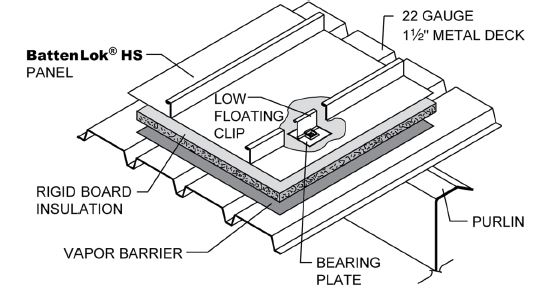
In this insulation approach, rigid foam insulation board is used to achieve the sought after energy performance. Commonly, these use metal deck panels over the roof structure thus supporting the insulation and a vapor retardant material on top of the deck. The insulation and the metal roofing can then be secured to the framing substructure or to the metal deck itself, which means the details of attachment need to be reviewed and engineered to avoid adverse affects on the roofing system.
Minimum decking gauge, clips spacing and clip screw lengths should be considered as well as associated adjustments to labor costs.
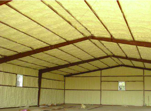
Spray-on Insulation:
All of the above systems typically require attention to providing additional air and vapor barriers and proper cutting and fitting during installation so as not to cause unwanted infiltration or to prevent condensation from occurring. For these reasons and more, some people will consider the use of closed cell spray-on foam insulation, which can continuously provide all of these features in one product. It can also be installed after the roof is completed and structure is weathertight.
Any corrosion of the panel due to adhesion of the insulation is not covered by the panel.
In the case of metal buildings, spray-on insulation is typically applied in the field onto the inside face of installed roof panels and sometimes wall panels too. There are, however, a few concerns with this approach in metal buildings. First, if conditions are not right and the panels are not properly prepared, then the spray foam can, in fact, trap moisture between the insulation and the metal components it is sprayed onto. That can lead to corrosion of the metal or deterioration of the insulation. Secondly, not all spray foams on the market are intended for this type of use so they don’t always adhere well to some metal panels, meaning it could become loose and fall away. Finally, continuous spray foam in this application will not always be able to expand and contract at the same rate that metal does. In some cases, that could mean that the foam suffers from differential movement causing it to break or lose adhesion.
For all of these reasons, be certain to research all options before considering or selecting a foam spray-on insulation that will not negatively impact your roof performance. If a foam insulation is preferred, it may be worth considering the use of insulated metal panels (IMPs) that are designed, engineered, and fabricated to be compatible with metal building construction.
Recognizing all of the above variations and options, the key point to remember about insulating metal buildings is the importance of communication between those designing and ordering an insulated metal building and those who are manufacturing and fabricating it. To find out more about the best ways to do that, contact your local MBCI representative.
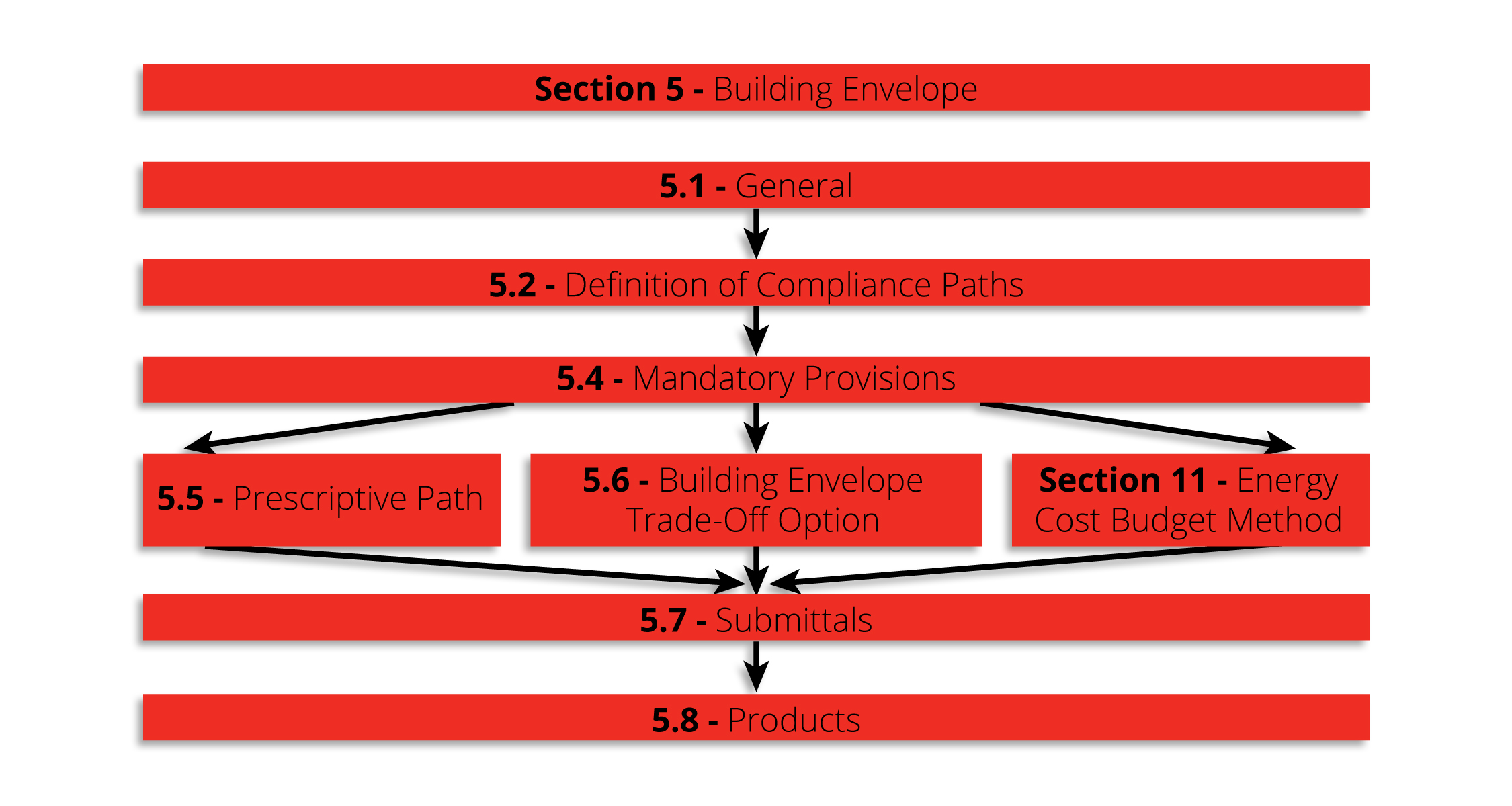
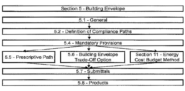
For a given assembly, if the right information is not specified in conjunction with the desired R-value, the designer will likely not achieve the results he or she expects. This can lead to code compliance issues as well as poor performance of the finished building. Therefore, a more thorough approach must be considered to ensure the specified assembly will be building energy efficiency code compliant. Where to begin? When looking at proper test methods to determine thermal resistance of metal panels, the place to start is ASHRAE 90.1 Chapter 5 (Building Envelope) and Appendix A.
ASHRAE 90.1 Section 5 specifies requirements for the building envelope.
Code Compliance for Thermal Resistance
The most widely accepted energy efficiency standard for commercial construction in North America is ASHRAE Standard 90.1. This standard provides both a prescriptive and a performance path to be chosen at the designer’s option. The prescriptive path is most commonly used. It also provides the baseline performance level that is used to determine compliance for the performance path, so understanding this set of requirements is critical. Within the prescriptive path, two possible methods of compliance are available to determine the minimum thermal performance of opaque areas on the building envelope. Section 5.5.3 is the pertinent passage and it reads:
Minimum rated R-values of insulation for the thermal resistance of the added insulation in framing cavities and continuous insulation only. Specifications listed in Normative Appendix A for each class of construction shall be used to determine compliance.
Maximum U-factor, C-factor, or F-factor for the entire assembly. The values for typical construction assemblies listed in Normative Appendix A shall be used to determine compliance.
Exceptions: For assemblies significantly different than those in Appendix A, calculations shall be performed in accordance with the procedures required in Appendix A.
What does this mean? Basically, there are standard types of construction that ASHRAE recognizes and if you have a wall that fits the description in Appendix A, you don’t have to test or do anything special to determine its thermal resistance. Appendix A provides tables based on calculation methods that have been derived on the basis of previous tests and general experience. What is perhaps less obvious is that if your assembly is adequately described by one of the standard assemblies in the Appendix, you may NOT use a tested or modeled value in place of the values in the table, even if that value has better performance! (i.e., lower U-factor) This is explained in Section A1.2.
The reason the code is set up this way is to prevent people from building unrepresentative assemblies that achieve high performance in the lab but are likely not built to the same specifications in the actual building.
Conversely, if the assembly you want to use is NOT adequately described in Appendix A, the appendix goes on to specify which methods are acceptable to determine the U-factor based on the assembly to which it is most similar. This is covered in Section A9. Two and three-dimensional finite element models are always acceptable and in some cases, simplified calculation alternatives are also available. Note that hot box testing is not always allowed.
Conclusion
To summarize, whether using a prescriptive or a performance path, the first and last stop when determining thermal resistance for metal panels is ASHRAE Standard 90.1 Chapter 5 and Appendix A. Designers would be well advised to familiarize themselves with the Standard and the specific set of requirements for their particular scenario in order to utilize proper testing methods for high-performance results.
Insulated metal panels (IMPs) used for building envelopes offer great simplicity in terms of enclosing a building in an attractive, energy-conscious manner. However, they require somewhat different thinking in terms of design and installation compared to conventional single skin panels on metal building with separately installed fiberglass insulation and vapor liners. That’s because, while the insulation aspect of IMPs is well controlled in the factory, the air and vapor sealing aspects are entirely in the hands of the installers in the field.
Why is vapor sealing a concern? Because it can make or break a building envelope. Airborne moisture that travels through seams, joints, or gaps between IMPs or between the panels and the structural steel can condense and wreak havoc on the integrity of the wall system. If that condensed moisture makes its way to unprotected edges of metal, then rusting, staining, and deterioration can occur. If it collects and drains out the bottom of the panel, then a building owner may mistakenly think that the IMPs are leaking water. If the moisture works its way inside a panel and becomes trapped it could freeze in cold climates or applications, and push panels enough to make unsightly or fail to perform as intended.
How does an installer of insulated metal panels avoid these issues? By properly using sealants as recommended by the IMP manufacturer to close the gaps and assure a vapor-tight installation. Here are the key things that installers need to pay attention to:
Sealant Types
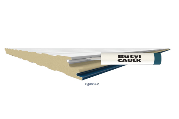
In most cases, butyl caulking is the recommended sealant for panel joints and perimeter attachments, although urethane sealant may be called for in some cases. For fire-rated panels, silicone sealants are usually required. The important caveat for all of these sealants is that they are most successfully installed when they’ve been stored within acceptable temperature ranges. In cold weather, they may need to be kept in a warming bin; in warm weather they must be kept out of direct sunlight.
Apply continuous non-curing butyl sealant to the interior panel joint with a bead size of approximately 1/4″ as shown above.
Tools to Use
Applying any of the needed sealants will require using the proper tools. Manual caulking guns don’t provide the consistent quality of application needed, so electric or pneumatically operated applicators are required.
Sealant Location
For typical building applications (non-freezer/coolers), the vapor sealant is placed in the interior panel joints when IMPs are installed vertically. For refrigerated spaces, the sealant is commonly placed on the exterior. If the IMPs are installed horizontally, then it usually is sealed on both the interior and the exterior panel joints to help with weather sealing as well. Note that the final placement of the sealant, as well as type and location, is actually the responsibility of the mechanical contractor/architect and not the panel supplier as it is to be based also on the mechanical design of the building envelope. In addition, the entire perimeter of the panels where they meet the building structure needs to be sealed. This includes the base flashing, interior corner trim, and eave struts. Further, marriage beads of butyl sealant must be placed at all panel terminations.
Panel Installation – Sealant
Sealant Continuity
In order to be effective, all sealant and caulking must be fully continuous. That means that the thickness of the sealant bead must be consistent and thick enough to fully close all gaps between or around IMPs. It should not be overdone, however, since too much sealant will ooze out between panels that are pressed together, causing a bit of a mess on one side of the other. Sealant continuity also means that it can not be interrupted due to poor adhesion. Therefore, before any sealant is installed, the application surfaces must be cleaned and dry to be sure that full adhesion is achieved. Always check with the panel suppliers details for minimum bead size and critical locations.
Factory-Installed Option for IMP
Some IMP manufacturers offer the option of having sealant pre-installed along the edges of the IMPs. Since the panels are wrapped and sealed for shipping, the sealant is protected and should be ready for use onsite. However, in this case, it is incumbent on the installers to handle the panels quite carefully, since the inadvertent placement of a hand over the sealant can damage it or deform it enough to render it ineffective. This factory-installed option offers a labor saving in the field but must be checked during installation and can be impacted by time climate depending on the time of year. Field application, while requiring more labor, does provide greater onsite flexibility for installers. Nonetheless, in all instances, the installer must ensure the sealants are properly located.
By paying attention to the details of sealing and caulking, a metal building constructed with IMPs will be a quality installation that will hold up quite well over time. To find out more about IMP metal products and systems that can help your next building be more vapor- and weathertight, contact your local MBCI representative.
When designing and constructing metal buildings, an increasing number of professionals are using a computerized building information model (BIM) as their primary tool. This allows for detailed, three-dimensional computer models to be created, not only to develop the design, but to identify material lists, coordinate details, avoid conflicts between building systems and streamline the design and construction process.
Problem: BIM Coordination
Of course, design is a process that requires some back-and-forth between multiple parties to arrive at the best final solution. So, when a metal-building supplier or manufacturer is asked to provide their information to be incorporated into a BIM process, the question that naturally comes up involves the level of detail. This is common across all trades, and fortunately, there is an organization that is addressing this issue. Known as the BIMforum (www.BIMForum.org), is is the not-for-profit United States chapter of buildingSMART International, and its mission focuses on improving BIM technology, collaboration, education, innovation and open information exchange. As they describe themselves, “Co-sponsored by the Associated General Contractors of America (AGC) and the American Institute of Architects (AIA), BIMForum seeks to lead by example and synchronize with counterparts in all sectors of the industry to jointly develop best practice for virtual design and construction.”
Solution: Level of Development (LOD) Specification
A flagship publication of BIMForum is the 2016 version of Level of Development (LOD) Specification. Having evolved over several years, this publication is “a reference that enables practitioners in the AEC Industry to specify and articulate with a high level of clarity the content and reliability of Building Information Models (BIMs) at various stages in the design and construction process.” Coordinated with other industry standards, it “defines and illustrates characteristics of model elements of different building systems at different Levels of Development.”
Essentially, it defines and standardizes how much detail is expected in a building information model at different stages of design development. Therefore, if a metal-building manufacturer or any other trade is asked to supply its BIM information, then it needs to ask “What Level of Development?” so that is it providing the right amount of information to coordinate with the larger computer model for the building.
How LOD Works:
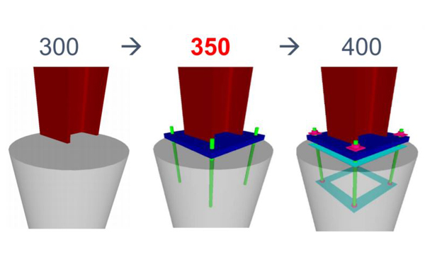
The LOD Specification is based first on the familiar Uniformat specification sections used by most spec writers. Metal Buildings commonly fall under Special Construction in Section F1020.40 in the Uniformat approach, or 21-06 10 20 40 in the Omniclass approach, and are found that way in the LOD Spec. From there, five levels of detailing are described by the numbers 100, 200, 300, 350 and 400, as described further below.
LOD 100 – This is the most basic of model, described as “Generic mass of special structure with system typically noted with a design narrative for conceptual pricing.” It is likely that this level of BIM is already developed by an architect or engineer and given to a manufacturer or supplier as a starting point.
LOD 200 – This level calls for basic primary structural member sizing, generic representation of secondary framing, and general cladding and exterior trim to be provided, including openings.
LOD 300 – More-specific sizing of all needed primary frame structural members, web tapers, frame connections and similar details are called for at this level. Similarly, secondary framing needs to be shown, including purlins and bridging, girts, subframes and base conditions. Exterior panel and trim with actual profiles, actual openings and all significant trim and accessories are shown here.
LOD 350 – This level starts to show coordination with other elements or building systems. Therefore, for the primary structure, things like base plate locations, bracing/gussets, clips and any reinforcement all need to be included. Secondary framing elements need to include similar details, such as nested members, connections to primary structure, any miscellaneous or secondary steel members, bridging, etc. Cladding and exterior trim would include all actual profiles, closures, downspouts and all minor trims shows at least generically.
LOD 400 – This is the full-fabrication level equivalent to shop-drawing level of detail. As such it includes all final details, including welds, bolts, holes, cinching and all other details of fabrication and assembly for primary and secondary framing, plus all cladding and trim.
Level of Development (LOD) Specification Example – image courtesy of BIMForum.org
By using these standardized Levels of Development, all design and construction professionals can proceed in an orderly sequence to provide the appropriate information, receive coordination feedback and then move on accordingly to the next level.
The full 2016 LOD Specification can be downloaded for free at http://bimforum.org/log/. The specific information for Metal Building Systems can be found on pages 177–186. For information on how to work with a manufacturer to provide the appropriate BIM information, contact your local MBCI representative.
Described in their most basic terms, R-value is a measure of heat resistance, while U-factor (also know as U-value) is a measure of heat transfer (heat gain or loss). The lesser known K-factor is simply the reciprocal of the R-value of the insulation divided by the thickness. What they all have in common is a relationship to the effectiveness of insulation material in resisting heat flow through a roof or wall element. There are different ways that this would be spec’d from a manufacturer to an architect or engineer. While the terminology might be familiar, the specifics are not always as clear cut as they seem. Understanding the differences will allow architects to make smart and effective choices to suit a given project’s needs.
Let’s consider some of the variables that might have an impact on what to look for and which metric to spec. As means of illustration, put yourself in the shows of a fiberglass or insulation supplier. You have a product, you know what it’s rated to, you know what the performance capability is, it’s been spec’d out to you—and you submit the bid based on those factors. But at that point you inevitably lose control over how the specs would actually get implemented. For instance, the architect may take that spec and incorporate it into a wall where it’s not used the most efficient way. This may not even be the result of a mistake; it could just be that other project elements have taken over.
Choosing the right insulation for the project can provide the building significant energy savings.
A good example would be stud walls. The fiberglass insulation supplier might indicate a given R-value, such as R-19. This would be the heat resistance value. The architect might spec and submit that bid to supply x number of square feet of that insulation based on that R-value. However, it could be cut or delivered in rolls and designed to fit between the metal studs. Metal studs are much more conductive than insulation and they provide an alternate path for the heat to flow through the assembly, almost irrespective of what the R-value and insulation is. Given these factors, the architect might have to make tradeoffs.
Choosing U-Factor
Because of all the variables encountered with R-value, U-factor is actually more recommended and reliable, and it more appropriately meets code requirements.* The concept of U-factor relates to the heat transfer coefficient but is described in the code as total heat flow per unit area through the assembly inclusive of all the short circuits as it is planned out to be built. So, an architect or engineer would know the stud spacing, the cladding material, the interior finish material and the R-value of the insulation. With that information in hand, one can go to a textbook, ASHRAE 90.1 or the ASHRAE Book of Fundamentals and find the U-factor for the assembly. It is this U-factor that is actually compared against the code requirements. It’s a better way to spec because it already takes into consideration all those things that come into play and encourages the use of suppliers (such as MBCI) that staff people who can help do those calculations or give assistance as opposed to saying, “I need R-19” and then wind up with a building that’s bridged or has more short circuits than anticipated—and having the building not perform as needed. This, in essence, is the key difference between R-value and U-factor.
A Word About K-Factor
As for K-factor, as noted this is the thickness of the insulation divided by the R-value. Its intention is to spec out an insulation when you’re not entirely sure what thickness it will be at the time you spec it out. This is fine for design-build scenarios but not a good practice for a hard bid. Bottom line: U-factor is most often the most reliable choice.
*Note: The code defines U-factor as discussed but underlying heat transfer theory may describe U-factor as 1/R-value. Insualtion suppliers might invert it and make it an R-value (but doesn’t take all the variables into consideration). Therefore, an architect would be advised to specify a “U-factor in compliance with ASHRAE, ” which includes thermal bridges, joints, etc.
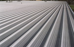
When installing metal roof panels, the sign of a successful installation can be seen in the way the spacing and alignment of the panels are held across the entire roof. Improperly done, the appearance suffers from standing seam lines that are wavy or non-parallel to roof edges. Even worse, the panels can be unduly stressed, causing the potential for failure of water protection. Installed properly, by being diligent about spacing and holding the modular layout to be square to the building, the results are clean, straight lines that allow proper performance of the roofing system.
Here are some basic tips for installing metal roofing panels that help ensure that the module is used as an advantage for first-class work.
Check the Building
Before starting the roofing installation, examine the steel structure and anything else that the roofing panels attach to or are impacted by. Is the steel out of square? Are the purlins properly aligned or are they bowed? Is the plane of the substructure within the tolerance of the manufacturer’s requirements? Discovering any irregular conditions in the building will require some adjustment to determine how to assure that the roofing can be installed properly and then remedy prior to starting.
Establish a Reference Line
The best way to ensure that the panels stay aligned as they are installed is to establish a fixed reference line along the rake edge of the building that is square to the building eave. Then, all measurements for spacing should be made from this reference edge line. A string line can be installed from the eave to ridge running parallel to the rake. The string line should stay ahead of the work and measure from the string back to each panel run. The string line is moved ahead as the roof installation progresses.
Improperly installed roof panels that do not maintain proper module alignment not only look bad but will result in a roof system not being able to function as intended for expansion and contraction as well as weathertightness.
Checking Panel Alignment
The alignment of the roof panels can be checked every run, but at a minimum, it must be checked every three or four runs. Measure from the rake support to the seam of the last completed panel run at the eave, endlap and ridge.
Holding Panel Modularity
Here are a few basic techniques as the work progresses:
For better clip alignment, the installer can pre-drill purlins at endlaps and ridge locations. The hole should be located at the leading edge of the clip so that an awl or punch can be inserted into the hole to align the clip and adjust accordingly.
In order to be sure the panel shape is held, use wood or other substrate to create blocking that can be inserted between the panel ribs and used in conjunction with checking the module and alignment of the panels as they are installed.
Keep as much weight as possible off of the panel while installing clips. Not only is it unsafe, but it can shrink width of the panel.
Use the correct combination of clips, insulation thickness and thermal spacers to maintain a level panel installation and prevent gaining or losing module size. See the manufacturers recommendations for each of these components based on the roof insulation system being utilized.
Use alignment straps purchased from the roofing manufacturer and install them on top of the purlins before insulation. These are factory stamped to receive the roof system clips based on their panel module.
A properly installed system is apparent in the consistent alignment of the roof panels with the building and will perform as designed more many years of weathertightness.
Adjusting Panel Width
In order to maintain the modularity of a well-installed roof, the width of the panels may need some slight adjustments. Some roof systems can be adjusted by bending the sides of the backup plates slightly to make the panel connection at then endlaps and ridges either wider or narrower, but no more than ¼” per side. Other roof systems may be adjusted with the panel clips themselves. To stretch the panel width, install the clip at the endlap or ridge with the base angled away from the panel. To shrink panel coverage, install the clip at the endlap or ridge with the base angled toward the panel.
By following some of these simple techniques and paying attention to the reference lines for the roof, any deviations and corrections can be identified right away rather than discovering the problem later and requiring rework. Overall, these tips should result in a roof that is better-looking, faster to install, and more weathertight.

