Daylighting 101

In the age of increased energy efficiency requirements in buildings, designers often find themselves spending time and resources squeezing performance out of systems with relatively little gain in efficiency. More and more, building insulation systems seem to fall into this category. The authors of the building codes recognize this as well and have reacted by turning their focus on other metrics like air infiltration where more substantial gains are to be had. A similar situation exists with lighting efficiency. However, when it comes to daylighting, designers are often pushed out of their comfort zone because lighting concepts and terminology is quite esoteric and difficult to comprehend.
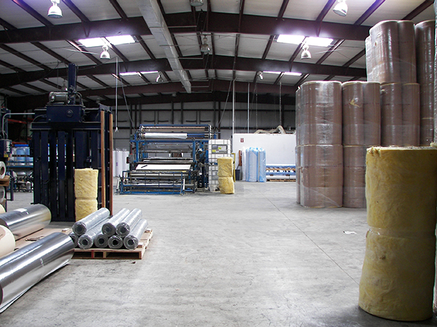
Daylighting
m
The truth is that most people take light for granted and aren’t aware of the complexity of lighting for human activity and comfort. Probably the biggest reason for this complexity is the fact that the human eye is the only way we can judge light and although the eye is an evolutionary masterpiece, it has its own idiosyncrasies and no two eyes work identically. For instance, the typical human eye can discern shades of green at much greater accuracy than other colors and because of this sensitivity, green light is often perceived as brighter than other colors at the same energy level. Therefore, quantifying light level for human comfort and function must take this sensitivity into account, leading to some complexity. Here are some basic principles that you need to understand:

A steradian is a unit of solid angle measure. You can think of a 1 steradian solid angle as a cone cut out of a sphere with the apex of the cone at the center of the sphere and cross-section angle of approximately 66 degrees. A unique property of a 1 steradian solid angle is that the area of the semispherical “cap” captured by the cone is equal to the radius of the sphere squared. This makes it a convenient shape to use in measuring the amount of light projecting from a source at the apex of the cone through its interior and onto the cap because the amount of energy passing through any cross-section along the way is always the same. There are 4π, or approximately 12, steradian in a sphere.
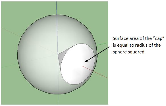
Surface area of the "cap" is equal to radius of the sphere squared.

Light is generated at the molecular level by the outer bands of electrons surrounding a given atom. When these electrons become excited at a high enough level, they emit a burst of energy in the form of electromagnetic radiation of a wavelength interval unique to the emitting atom in order to return to a lower energy state. If the energy level is just right, this wavelength will be in the visible light spectrum and viewed as a specific color. White light is formed when many atoms respond at various energy levels distributed across the entire visible spectrum in a pattern such that the energy transmitted is roughly constant with wavelength. The human eye is not responsive enough to discern the different colors hitting it, so an overall stimulation results in a static or “white” response. (There is a similar concept for sound as well, called “white noise”, when the ear cannot detect the individual vibration frequencies.)

The absolute brightness of light is given by the total energy it transfers through electromagnetic modulation. It is determined by summing up the energies transferred by each incorporated wavelength. As light travels from a point source, this energy spreads, causing the amount of energy arriving at a single point in space to decrease as that point is placed farther away from the light source. Brightness decreases with the square of the distance from which it is viewed. In other words, a light will appear ¼ as bright when viewed from a distance twice as far.

Because the human eye is more sensitive to green light than other colors, the brightness it perceives from different lights can only be effectively compared at the same color or wavelength. For light used for human function and comfort, it has been standardized to quantify the brightness at the 555 nanometer wavelength, which is near the center of green in the visible light spectrum, and then adjust for the effect of other colors consistent with how the human eye perceives them. Color is accounted for by weighting the energies transmitted at other wavelengths using the luminosity function. The resulting quantity is called perceived brightness. The luminosity function is similar to a bell curve and it represents how relative brightness of various colors is perceived by the typical human eye. As you might expect, the luminosity curve peaks at a wavelength near 555 nanometers.

Absolute brightness is measured in watts and should only be used when comparing lights of the same color. This should not be confused with power consumption, which is also measured in watts. Perceived brightness is instead expressed in candela and is the only way light of mixed color (on non-monochromatic) can be compared. A one candela light source with a wavelength of 555 nanometers transmits 1/683 of a watt of energy.

It is also important to be able to quantify total light output of a light source. Real-world light sources are not usually of equal brightness in all directions, so candela is not the best measurement to use. To account for spatial variation, total light output is defined as the sum total of light passing through every point in a cross-section of a one steradian solid angle, considering a light source at the apex, divided by the area of the section. This results in the same quantity regardless of the location of the cross-section. So, if a light were to transmit one candela through each point in the cross-section of a unit steradian, then it would be said to produce one lumen of light. Likewise, a 555 nanometer light source radiating one watt per steradian of energy produces 683 lumens.

Finally, the effect of light projected onto a surface must be defined, commonly called illumination level. If a light projects through a solid angle of one steradian at a uniform perceived brightness of one candela, the illumination level achieved one foot away is called a footcandle. This definition confuses many people because it is contrary to what the name might imply. But because a unit steradian is used as the basis, a footcandle equates to one lumen per square foot and it is generally much easier to think of illumination level in this way. Lux is the metric equivalent to a footcandle and there is about 10.8 lux in a footcandle. Since illumination level differences of one tenth of a footcandle are not detectable by the human eye, this is often simplified to 10 lux per footcandle.

To put this all into context, a dome skylight 24” in diameter, elevated a foot above a 30’ high roof on a 20’ x 20’ grid on an open building in El Paso, Texas, achieves about 25 footcandles at a level 4’ above the floor at noon on March 21st (typical spring equinox). Compare this versus the following recommended illumination levels for various tasks as recommended by The Whole Building Design Guide:
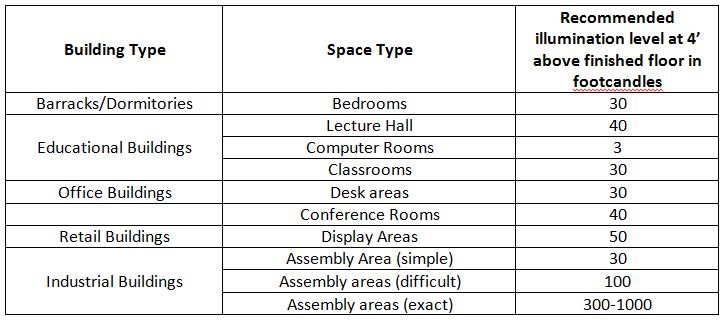
Whole Building Design Guide Illuminatin Levels

Understanding these concepts will help you get more out of MBCI’s latest whitepaper, Shining Light on Daylighting with Metal Roofs, where MBCI explores the subject in detail, wholly within the context of metal roofs and metal wall systems. We hope you find it…err, enlightening.
Download the White Paper, Daylighting with Metal Roofs

How to Help Prevent Oil Canning

Oil canning is defined as the visible waviness in the flat portion of a metal panel.  Oil canning is a visual issue, not a weatherproofing or performance issue.  However, building owners will complain about waviness in metal panels on roofs, walls, and perimeter edge metal.  Edge metal and metal wall panels are more of a concern than low-slope metal panels because edge metal and wall panels are visible from the ground.  Steep-slope metal panels and shingles are also visible, so awareness of potential oil canning is important.

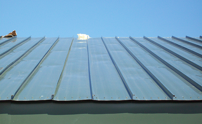
Oil Canning on a Metal Roof

What Causes Oil Canning?

Oil canning can happen when unwanted stresses are introduced at fasteners, clips, and over purlins and uneven substrates.  Over-driven fasteners, clips that are slightly misaligned relative to the clip/seam interface, and too much insulation between the purlins and panels can introduce these unwanted stresses.  A misaligned panel or edge metal clip, certainly after the seam or drip edge is crimped tight, will add stresses to metal panels and edge metal

Tips to Help Prevent Oil Canning

  1. Place clips correctly: Setting clips in the proper location for edge metal and metal panels (roof and wall) is critical.  The clip needs to fit into a panel seam without forcing the vertical seam out of plane.  The clip needs to be aligned correctly and sized appropriately to not compress the vertical portion of the seam.  Clips that secure edge metal need to be positioned correctly so that crimping the drip edge won’t twist or bend the edge metal.
    Although not highly visible, low-slope structural panels can oil-can at clip locations and where insulation is draped over purlins.  Compressed insulation at purlins can “push back,” adding stress to the panel and resulting in oil canning.
  2. Consider the roof color: Sometimes oil canning is inevitable.  The color of the metal or coating won’t really make a visual difference, but darker colors panels will heat up more in direct sunlight.  This may make oil canning worse in some cases.  However, striations and small ribs (which also add strength) may help prevent or hide oil canning.
  3. Choose a thick metal: Metal thickness matters, so specify metal that’s as thick as possible to avoid oil canning.  Thicker metals are stiffer, so they may resist deformation due to unwanted stresses.  This reduces the chance of oil canning in edge metal and wall panels, which are most commonly smooth-surfaced.

For more information on oil canning and its causes, see the Metal Construction Association’s white paper on the subject, which can be found at www.metalconstruction.org.

Consider these ideas on your next job.

Snow and Metal Panel Roofs: Part 2


In part I of this blog, we discussed what to consider when deciding the roof material and roof slope to build with in snowy conditions. If you have decided to design a roof with metal panels, it is important to use the correct panel seams, evaluate the roof layout and consider long-term weatherproofing, and ensure your roof design fits the needs and function of the building.

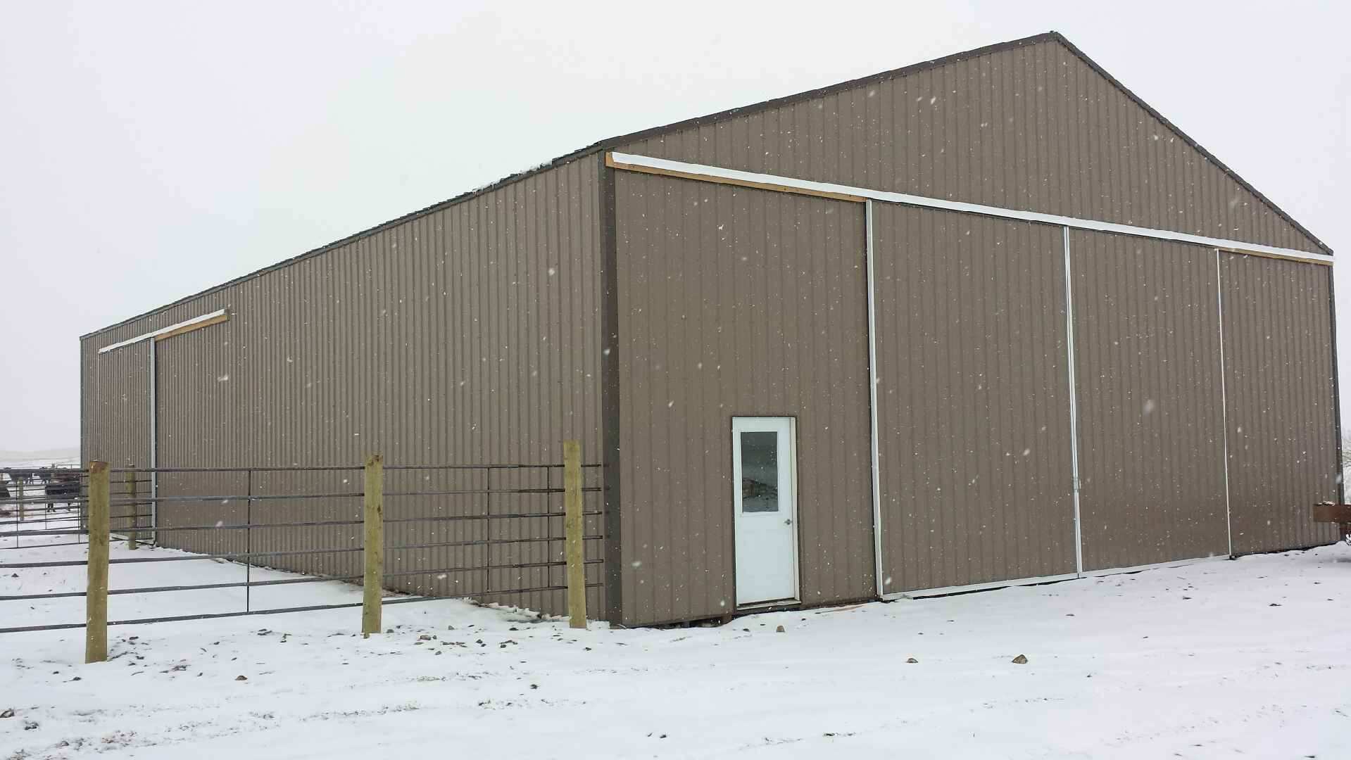
Metal Building in Snowy South Dakota

Weathertight Panel Seams

For metal panel roofs less than 3:12 (i.e., low-slope roofs), the panel seams should be watertight. A watertight seam resists water intrusion, so snow on a roof should not become a leakage issue. For metal panel roofs with slope greater than 3:12, the steeper slope means liquid water (e.g., rain) drains very quickly off the roof. Because of this, many seams used for steep-slope metal panels are not watertight. Non-watertight seams can be problematic where snow stays on a roof. Architects should consider using watertight seams (e.g., double lock) and highly water-resistant underlayments in snow areas for all roof slopes.

Roof Layout

A designer should also consider the layout of the roof. Valleys collect snow. Valleys in which one roof area is significantly larger than the other (e.g., a dormer extending from a large roof area) are vulnerable to unbalanced sliding snow. A large snow slide can move across the valley and literally tear open the standing seams and displace panels.

Drifting snow can occur behind HVAC units, at perimeter walls and behind rooftop solar thermal and PV panels. Where a roof transitions from a lower low-slope roof area to an upper steep-slope roof area, snow will collect. Consider the potential snow load and entrapped moisture at these locations; the transition detail becomes critical to long-term weatherproofing.  And, depending on the orientation (e.g., north facing), areas with drifted snow may not see much sunlight, so snow is more likely to stay on the roof for a longer time.

Building Function

As the roof designer, design the building and site to account for the roof’s function. Many designers turn to snow retention devices to keep snow on roofs, especially above pedestrian areas, such as entrances and outdoor seating areas, or adjacent buildings.   Some of these devices rely on adhesive attachment to the panel, which means they rely on the adhesion of the paint to the metal. But physical attachment—e.g., snow fences clamped to the standing seams—is always a more confident, long-term approach than adhesive attachment when it comes to resisting shear/sliding loads. Using.multiple rows of snow fences, sometimes double in height, may be needed in areas that get large and prolonged amounts of snow (e.g., ski resorts), or where the eave to valley length is long, or where the slope is very steep.  Each increases the shear loads.

Designing a Snow Retention System

Snow retention systems need to be engineered, not guesstimated! Use online models to assist with designing snow retention devices. Input your snow load, roof slope, panel width, roof length (measured horizontally), overall width of the roof area, and the manufacturer and panel type. These inputs are needed to adequately engineer a snow fence assembly.  And remember, the snow loads are transferred from the fence to the panel seams, then to the panel clips and to the deck/structure.  The entire load path needs to be designed to handle the snow load.  Here is one model: http://www.s-5.com/calculator/index.cfm

For more tips on designing a snow retention system, read “The Art of Properly Specifying Snow Retention Systems.”

Designing a metal roof for snow is a mix of logic, experience and engineering. We can design roofs in snow because of our everyday observations of roofs with snow on them. Stay observant; design well.

Snow and Metal Panel Roofs: Part I

It’s February; winter storm Jonas happened last month. Snowstorms will continue to occur, and heavy snowfall can have many negative effects on roofs. What should you consider when designing a roof in snow areas, especially those with high snow amounts?

Rustic Trail Blog

What to Consider when Building Metal Roofs

Roofs on buildings in snow areas—from a structural capacity point of view—can be designed to be any low-slope or steep-slope roof system. Roof structures can be designed and built to accommodate any anticipated snow loads. From a weather-protection point of view, snow buildup on a roof can be problematic. The extra load and the risk of leaks are not desirable; however, keeping snow on a roof is often the acceptable way to deal with it.

Roof Slope

Unquestionably, the slope of the roof matters when it comes to snow staying on or sliding off. Once a roof slope gets to be about 45 degrees (i.e., 12:12), slope becomes the overriding factor for sliding snow. The amount of snow and the roof type also matter. From a designer’s perspective, there are also a number of localized issues to consider when designing for snow on roofs.

Snow Density

The amount and density of snow also matters. More snow means more weight. More weight means a greater sliding force down (along) the slope of the roof. On slopes less than 45 degrees (e.g., 6:12 to 9:12), a low coefficient of friction (such as on smooth pan metal panels) means less resistance to sliding. Striations and embossing add a small 3D profile and improve the resistance to sliding, especially if they run transverse to the slope.

When heavy, dense snow slides it can pack a punch. Such snow sliding down a roof can shear off exhaust vents; therefore, rigid vent pipes are needed, along with a secure method of attachment. Further, installing vent pipes as high up on the slope as possible reduces the amount of potential shear load. Consider the potential load on a vent pipe that’s 5 feet from the eave with a 40-50-foot eave-to-ridge length! Reverse that and most of the load goes away.

Roof Material Type

Material type and surface color make a difference, specifically a roof’s emissivity. Metal roofing absorbs heat more quickly and radiates heat more effectively than most other roofing materials. Darker colors enhance this effect. Even with as much as 3 to 5 inches of snow, UV light passes through it; less light passes the denser the snow. (The proof: solar energy panels [photovoltaics (PV)] work when covered in some snow.) This effect only happens on sunny days, and is most effective on south-facing roof areas. If there is heat loss from the building up through the roof, the heat will help melt the snow at the roof/snow interface. This creates a potential for sliding snow.

In part II of this blog, I’ll discuss the logic, experience and engineering that goes into designing a metal roof for snow. In the meantime, learn how to properly install snow retention devices, and watch how a New Jersey home heats and cools itself by gathering snow and rainwater.

Myths About Metal Roofing: Heat, Wind and Lightning

Properly detailed and installed metal roofing is one of the most resilient, lasting, efficient and attractive kinds of roofing systems for commercial and institutional buildings. Yet there are plenty of questions about metal roofing, and building teams often find time in project meetings to address the most common, recurring topics and myths.

Facts vs Myths About Metal Roofing

I call these “mythbuster meetings,” because many of the questions are fabrications – concerns arising from less savvy professionals or from competitive “selling points.” Among the most prevalent untruths:

Myth about Wind Uplift

Myth: Wind uplift affects metal roofing more than other roofing types.

Reality: While the noncontinuous nature of metal roof attachments makes them susceptible to wind uplift concerns, most roofing types are prone to similar effects. ASCE/SEI calculations for wind loading and FEMA studies of storm areas have shown that properly applied metal roofing outlasts other roof assemblies during hurricanes and tornados.

Building geometry affects how well the roof survives, regardless of roof type. Engineering determines how many insulation board fasteners are needed, and the optimal and safest distances between clips for standing seam systems at corners and perimeters, where the forces are greatest. The interlocking or “active fastening” helps metal roofing pass severe wind and uplift tests including ASTM E1592, UL 580 and UL 1897, and the Miami/Dade County codes, according to a report from Stanford University.

Myth about Heat

Myth: Metal panels get hotter and have more thermal bridging because metal conducts heat so well.

Reality: Depending upon the surface finish, metal roofing can “provide enhanced energy efficiency with its solar reflectance and infrared emittance properties […] to meet the climate requirements of the building,” according to the Stanford University paper and research highlighted by the Cool Metal Roofing Coalition.

As compared to other roofing types, metal roofing tends to be highly reflective and is available with high emissivity. Insulated metal roofing panels have foam insulation that delivers R-values up to R-8.515 per inch thickness and total roof U-factors that exceed those of many other roofing types, helping projects meet strict energy code rules.

Myth about Lightning

Myth: Metal roofs are more likely to get hit by lighting than any other roof types.

Reality: That is bunk; simply untrue. You can read my detailed blog on the subject, or for serious mythbusters refer to the Metal Construction Association’s Technical Bulletin MCA13a, which gives a full and authoritative overview.

As the MCA summarizes, “Because metal roofing is an electrical conductor and a noncombustible material, the risks associated with its use and behavior during a lightning event make it the most desirable construction available.” That’s right: The best option for lightning risks.

I hope some of the above information provided insight and assurance about building with metal roofs. If you have any additional questions or concerns, submit them here to our technical experts.

Wind Designs for Metal Roofs

One of the most important requirements for metal roof installation is ensuring that a roof stays in place when the wind blows.  The core concept is that the roof’s wind resistance needs to be greater than the wind loads acting on a building’s roof.  Wind resistance is most commonly determined by a physical test; wind loads are calculated.

Calculating Wind Loads

Wind loads are based on the design wind speed (which is based on the geographic location of the building), height of the roof, exposure category, roof type, enclosure classification and risk category.  The height of the roof, and exposure and risk categories are factors that are used to convert design wind speed to an uplift pressure.  Wind speed maps and the rules to calculate wind pressures are found in Section 1609, Wind Loads, in the 2012 or 2015 IBC.  The information is based on an engineering standard written by The American Society of Civil Engineers, “ASCE 7-10, Minimum Design Loads for Buildings and Other Structures.”Wind Uplift Testing_2

Defining Exposure Risk Category

Exposure categories relate to the characteristics of the ground, such as urban and suburban areas or open terrain with some obstructions or flat areas like open water.  There are 4 risk categories.  Category I is low risk to humans, such as agricultural facilities. Category III includes, for example, buildings for public assembly, colleges and universities, and water treatment facilities.  Category IV includes essential facilities like hospitals and police stations.  Category II is everything else—most roofs are Category II. A building shall be classified as enclosed, open or partially enclosed. The enclosure classification is used to determine the internal pressure coefficients used to calculate design roof pressures.

Determining Wind Pressures

Contractors should work with a structural engineer or the metal panel manufacturer to determine the wind pressures for each roofing project.  Wind pressures are determined for the field of the roof, the perimeters and the corners, where loads are largest.  Only after determining the design pressures can the appropriate metal panel roof system and attachment requirements be designed.

Testing Uplift Resistance

Physical tests are the most common method to determine uplift resistance.  Panel width and profile, metal type and thickness, clip type and frequency, type and number of fasteners, and the roof deck contribute to the uplift resistance of every metal panel roof system.  Metal panel roof systems installed over solid substrates (with concealed clips or through-fastened) can be designed using the following test standards: FM 4471, ASTM E 1592, UL 580, or UL 1897.  Metal panels installed over open framing can be designed using either ASTM E 1592 or FM 4471.  Manufacturers run these tests; uplift resistance data is available for most metal panel roof systems.  Installers can get this data directly from manufacturers or from web-based listing services provided by FM and UL.

Designing a Legal Metal Roof System

Wind loads and wind resistance information is necessary to verify code compliance.  Get it for every project you install!  Using systems that not only have been tested to the correct tests, but using systems that have uplift resistance greater than the design loads is key to a successful installation, and quite frankly, key to installing legal roof systems.

Roofing Underlayment and Its Attachment Requirements

The International Residential Code (IRC) is commonly considered to be a prescriptive code, which means there are many requirements included that provide specific directions. Prescriptive-based code language provides a simpler method of enforcement for inspectors. And shouldn’t that be the case for one- and two-family dwellings, where well built and affordable is the goal?

Underlayment Requirements

In Chapter 9 of the 2015 IRC, the underlayment requirements for steep-slope roof coverings are included in three tables—material types, application and attachment requirements. Each table includes specific information for metal panels and separates out high-wind areas (defined as greater than 140 mph, and is only in the southernmost portion of Florida).

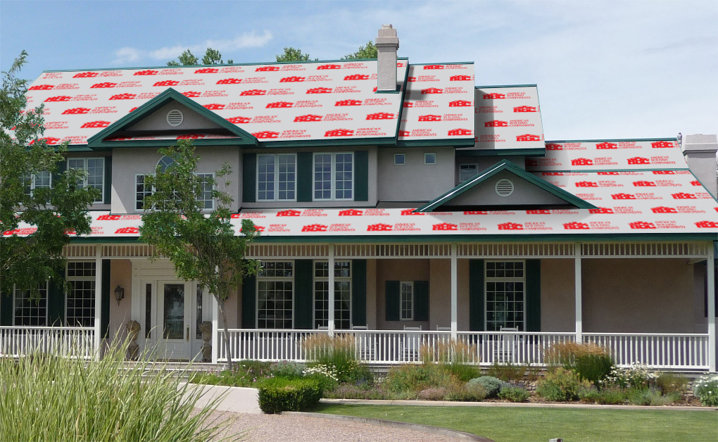
Roofing underlayment by our sister company ABC.

Material Type Requirements

Underlayment types for metal panels needs to only comply with manufacturer instructions. D226 and D4869 underlayments are viable options, as long as metal panel manufacturers allow them. And very importantly for metal panels, synthetic- / polymer-based underlayments are a viable option, again, as long as the panel manufacturer allows them to be used.

For metal panels in high wind areas, only D226 Type II and D4869 Type IV are allowed. In other words, only the heaviest materials are allowed in the highest wind zones.

Application Requirements

Simply put, underlayment should be applied according to the manufacturer’s installation instructions. For high-wind areas, specific application requirements are provided:

“For roof slopes from two units vertical in 12 units horizontal (2:12), up to four units vertical in 12 units horizontal (4:12), underlayment shall be two layers applied in the following manner: apply a 19-inch strip of underlayment felt parallel to and starting at the eaves. Starting at the eave, apply 36-inch-wide sheets of underlayment, overlapping successive sheets 19 inches, and fastened sufficiently to hold in place. For roof slopes of four units vertical in 12 units horizontal (4:12) or greater, underlayment shall be one layer applied in the following manner: underlayment shall be applied shingle fashion, parallel to and starting from the eave and lapped 4 inches. End laps shall be 4 inches and shall be offset by 6 feet.”

Underlayment Attachment Requirements

Underlayment should be attached according to the manufacturer’s installation instructions. For high-wind areas, specific attachment requirements are provided:

“The underlayment shall be attached with corrosion-resistant fasteners in a grid pattern of 12 inches between side laps with a 6-inch spacing at the side laps. Underlayment shall be attached using metal or plastic cap nails or cap staples with a nominal cap diameter of not less than 1 inch. Metal caps shall have a thickness of at least 32-gage sheet metal. Power-driven metal caps shall have a minimum thickness of 0.010 inch. Minimum thickness of the outside edge of plastic caps shall be 0.035 inch. The cap nail shank shall be not less than 0.083 inch for ring shank cap nails and 0.091 inch for smooth shank cap nails. Staples shall be not less than 21 gage. Cap nail shank and cap staple legs shall have a length sufficient to penetrate through the roof sheathing or not less than 3/4 inch into the roof sheathing.”

Self-Adhesive Underlayment Options

Of course, there are exceptions to these requirements. The first is to use a self-adhesive underlayment (i.e., ice dam protection) over the entire roof. The material needs to comply with ASTM D1970, “Standard Specification for Self-Adhering Polymer Modified Bituminous Sheet Materials Used as Steep Roofing Underlayment for Ice Dam Protection” and be installed per the metal panel manufacturer’s requirements. The code also points out that roof ventilation must be considered because a self-adhesive sheet is most often an air barrier and a vapor retarder. Concerns with moisture are quite relevant when these types of materials are installed over the entire roof deck. The second exception is to tape the seams of the roof deck with 4-inch wide strips of D1970 material, and then cover the deck with underlayment. The second exception is not widely used, except when trying to reduce, or eliminate, air flow through the deck while allowing moisture to escape.

IRC Requirements for Attaching Metal Panels

The IRC also includes some, but not many, requirements for the attachment of metal panels. The IRC requires metal panels be attached per manufacturer’s installation instruction and “be secured to the supports.” This implies fasteners should be attached to purlins or rafters, but one could easily argue the roof deck is the support for the metal panels. However, the IRC does provide specifics for fasteners used to attach metal panels, but the following is only applicable if manufacturer’s instructions don’t include fastener requirements. The IRC states:

“In the absence of manufacturer’s installation instructions, the following fasteners shall be used:

  1. Galvanized fasteners shall be used for steel roofs.

  2. Copper, brass, bronze, copper alloy and 300-series stainless steel fasteners shall be used for copper roofs.

  3. Stainless steel fasteners are acceptable for metal roofs.”

The Importance of Following IRC and Manufacturer Instructions

The IRC is a prescriptive code and there are many specific requirements for underlayment and metal panels. But because of the wide variety of styles, the IRC appropriately requires installation according to manufacturer’s instructions. It’s important to specify a new roof using both manufacturers’ instructions and IRC’s specific requirements. And, remember, a metal roof will have a long service life, so the underlayment’s service life should equal that of the metal roof. Don’t be shortsighted when designing for longevity.

3 Energy-Saving Technologies to Consider with Metal Roofs

A roof’s primary function is to keep a building weatherproof. A roof’s secondary function—and approaching nearly equal importance—is to be an energy-efficient element of the building envelope. From an energy efficiency standpoint, we’re accustomed to the inclusion of insulation. Are we as accustomed to the ideas that roof color and air leakage matter for energy efficiency? The building industry is embracing all of these technologies in an effort to save energy.  So how does an installer make it all work?

Insulation

NAIMA.org
Photo Courtesy of NAIMA

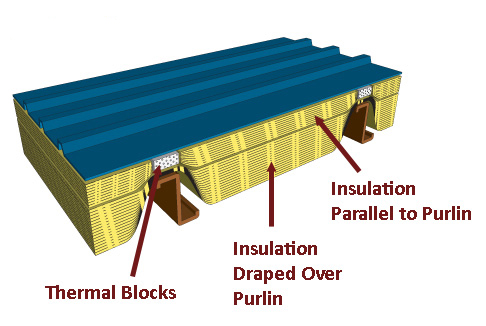
Insulation requirements for roofs on metal buildings (according to the 2015 IECC) range from R-19+R-11 LS up to R-30+R-11 LS, depending on climate zone. The first layer is draped over the purlins and requires a thermal spacer block with an R-3.5. A second layer is installed at perpendicular and is required to include a liner system (LS), which is a continuous vapor barrier installed below the purlins and is uninterrupted by framing members. The crisscrossed layers help reduce convective air movement within the insulation layer, making the insulation layer more effective. And, good news!—the vapor barrier can also be an air barrier. So, on to air barriers.

Air Barriers

Even small air leaks in buildings can account for a 30 to 40% heat loss during heating season (winter), regardless of the amount of insulation. It can’t be overstated—air barriers are critical to an energy-efficient roof and overall building envelope. The LS, or vapor barrier, can be an air barrier only if the seams of the LS are sealed to prevent air passage. The junction between the air barrier in the roof and walls is critical; it must be joined to be continuous. Often, a separate material (adhered membranes or spray-applied foams) is used as the transition from wall to roof. Or, the roof and wall air barriers might end on opposite sides of a perimeter beam or purlin, connecting the two air barriers. Also, any penetrations through the roof need to be sealed to the air barrier. Being continuous/having continuity is key to constructing a properly functioning air barrier!

Roof Color

We’ve heard a lot about roof color. Where air conditioning is prevalent (e.g., the Southwest), highly reflective roofs make sense, especially if there is minimal insulation. Where heating is prevalent, roof color becomes less effective for energy efficiency for a couple reasons. One, buildings require significant amounts of insulation, and two, there is much less direct heat gain from the sun over the course of a year. Where heating and cooling are both used regularly (e.g., Nashville, Chicago), it’s not a matter of “black or white.” There are many metal roof colors that are moderately reflective, so they balance reflectivity and heat gain as the seasons change.

Contemplate the interaction of insulation, roof color and air barriers on each metal roofing project.

Better Barriers: Meeting Thermal Performance and Controlling Air & Moisture

Panelized metal exteriors have joints. It’s just a rule of best-practice design. Yet these joints are seen by some as interruptions in the façade or roof, when in fact they are connections — the opposite, one can argue, of the word “interruption” that suggests a discontinuity.

Edie's CrossingIn fact, engineered metal panel systems offer arguably the best possible continuous exterior system. Not only are they properly applied exterior to the building structure—outboard of columns, joists and girts—but they are also designed to ensure an unbroken chain of thermal control and barrier protection. Combined with controlled penetration assemblies as well as windows, doors and skylights that are engineered as part of the façade and roof system, the insulated metal panel (IMP) products provide unequaled performance.
That’s the main reason that specialized facilities designed for maximum environmental barrier control are made of IMPs: refrigerated warehouses, R&D laboratories, air traffic control towers and MRI clinics, to name a few.

But any facility should benefit from the best performance possible with metal roofing and wall panels. Consider insulation shorthand for the code-mandated thermal barrier required for opaque wall areas in ASHRAE 90.1 and the International Energy Conservation Code (IECC). For a given climate zone, says Robert A. Zabcik, P.E., director of R&D with NCI Group, the project team can calculate the functional amount of insulation needed by using either the “Minimum Rated R-values” method or the “Maximum U-factor Assembly” calculation. For IMPs, teams use the Maximum U-factor Assembly, which can be tested using ASTM C1363.

With IMPs, the test shows thermal performance values up to R-8.515 and better per inch of panel thickness, meaning that a 2.5-inch-deep panel would easily meet the IECC and ASHRAE minimums.

With metal roofing panels and wall panels, a building team can achieve needed energy performance levels with this single-source enclosure, providing a continuous blanket of protection.

The same is true for air and moisture control. In a July 2015 paper by Building Science Corp., principal John Straube wrote, “Insulated metal panels can provide an exceptionally rigid, strong and air impermeable component of an air barrier system.” He noted that, “Air leakage condensation cannot occur within the body of the insulated metal panel, even if one of the metal skins is breached, because all materials are completely air impermeable and there are no voids to allow air flow.”

In terms of water control, Straube writes that IMPs have a continuous steel face that is a “high-performance, durable water control layer: water simply will not leak through steel, and cracks and holes will not form over time. The exterior location of the water barrier,” he adds, “offers some real advantages.”

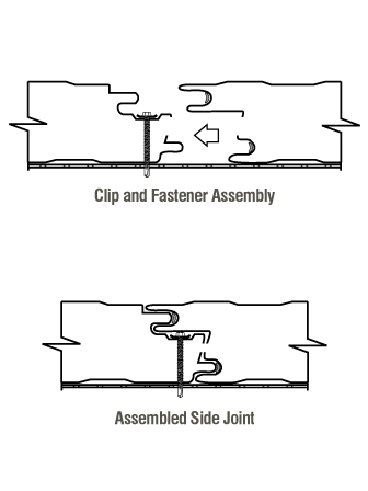
Clip-Fastener-AssemblyEnfold_blog

Connecting the panels at transitions, penetrations and panel joints is the key, of course. Straube notes that sealant, sheet metal, and sheet membranes are effective and commonly used to protect joints.

In my experience, these joint details are incredibly effective. They often outlast most other components of the building. Even more important, they help make IMPs better barriers that meet thermal, air and moisture performance needs. They help make metal panels one of the best choices of all.

Wellness and Envelopes: Four Ways Single Skin & Insulated Metal Panels Keep Us Healthy

SONY DSC


Is there a connection between building design and human health?

We know the answer must be yes, but figuring out how the connection works is the job of experts like the team behind the WELL Building Standard®, a new certification that takes on the question. Among the solutions that can help make a building better? Metal roofing and siding, according to many healthy building experts.

First, let’s learn about WELL. According to the International WELL Building Institute, the WELL Building Standard “takes a holistic approach to health in the built environment addressing behavior, operations and design.” Their performance-based system measures and monitors such building features as air, water, nourishment, light, fitness, comfort, and mind. Two ratings have been offered: WELL Certified™ spaces and WELL Core and Shell Compliant™ developments. Done properly, these “improve the nutrition, fitness, mood, sleep patterns, and performance of occupants.”

Pilot programs are currently available for retail, multifamily residential, educational, restaurants and commercial kitchens projects. In many of these projects, the use of metal claddings and insulated metal panels (IMPs) is recommended by many health-focused professionals. Why?

1. Occupant comfort

IMPs tend to have excellent R-values and very good thermal efficiency – including long-term thermal resistance, or LTTR, a key measure of how the building will perform over time. For the wellness factor from pure thermal comfort, IMPs are highly effective over conventional construction.

2. Nourishment of people and earth

IMPs are often made with recycled metals and improve the energy performance of the building. With energy cost savings ranging from 5 percent to 30 percent, they cut the carbon footprint of the facility. Plus the interior and exterior skins include up to 35 percent recycled content – and they are 100 percent recyclable – reducing impact on the global carbon load.

3. Daylight for all.

Using metal roofs with skylights or light-transmitting panels in conjunction with integrated dimming lighting is a highly cost-effective strategy, and IMP systems also have integrated window systems that increase available sunlight within building interiors. Light is essential for healthy buildings, and daylight is the best kind of all.

In addition, because rigid insulation per inch offers more R-value than per inch of fiberglass insulation and IMPs have metal liner skins, day-lighting fixtures such as light tubes can be integrated more easily with these roofs.

4. Proper moisture and air control.

Issues such as leaky walls and wet, moldy construction materials are anathema to wellness, and must be controlled for healthy building certifications. Mold has a negative impact on indoor air quality and indoor environmental quality, and one of the main culprits is trapped moisture. This can also corrode the metal studs and furring members, even if they are galvanized, leading to structural issues such as reduced fastener pullout resistance and leaks.

How Does a Building Become WELL Certified?

IMPs used as either rainscreens or as sealed barrier walls backing up a rainscreen are shown to protect against moisture issues and mold over time. They also serve as a continuous layer of insulation and air barrier. In this way, the single-component system can eliminate the need “for air barriers, gypsum sheathing, fiberglass insulation, vapor barriers, and other elements of a traditional multicomponent wall system,” says one industry executive. In fact, many masonry buildings are being upgraded with IMP retrofits on the exterior, directly over the old concrete, brick or stone.

All of these traits of IMPs certainly contribute to more healthy buildings, but do they add up to WELL Building certification levels, such as Silver, Gold or Platinum?

To get there, building teams must undergo an on-site WELL Commissioning process with rigorous post-occupancy performance testing of all the features. If it meets the “preconditions” — the WELL features necessary for baseline certification — WELL Certification is given. If the team pursues “optimization features,” the higher levels of achievement are granted.

Find a sales representative