Understanding Today’s Vapor Barriers

One of the most misunderstood aspects of a metal roofing system is the proper use of a vapor barrier. There are many sources of information about this topic – some of which are based on science, some based on anecdotal field experience, and some based on journalism. Here, we will try to break it down to the basic principles that can be used to understand the latest options for a metal building roof system today.

What is Vapor?

The observed science tells us that water can take three forms, depending on temperature and its ability to interact with other things around it. Water can be a liquid that we drink, solid ice that we can skate on, or a gaseous vapor that is part of the makeup of the air we breathe. We can’t see water vapor in the air but we can feel it – we call that humidity. High humidity means a lot of water vapor is in the air, typically coupled with higher air temperature – and both can make us feel uncomfortable and “sticky.” Low humidity means the air is dryer – more typical in lower-temperature air – but this may also be uncomfortable for our breathing, skin dryness, etc.

Why is Vapor a Concern?

As long as the gaseous water vapor stays in the air at a moderate or comfortable level, there is no real concern. However, since water vapor responds quickly to temperature, it can turn back into water as soon as it encounters a surface that is cold enough for it to make the transformation. We know this phenomenon as condensation, and anyone who has seen a cold drink collect water on the outside of a glass on a humid summer’s day has experienced it. It is the same phenomenon that shows up on the surface of windows in a building when there is a big difference between inside and outside temperatures. We know that the amount of water vapor (i.e., humidity) present and the air temperature can both be variable at any given time, but there is always a predictable point at which water vapor will condense and form water drops – this is called the dew point. When vapor in the air encounters a temperature at or below the dew point, condensation occurs.

What Does This Have to do With Metal Roofing?

Metal roofing systems and condensed moisture are not a good combination. If airborne moisture seeps into a metal roof assembly, finds a cool surface, and condenses on any surface there, it likely won’t be visible from inside or outside of the building. That trapped water can then cause rust and corrosion of metal parts, resulting in real damage. It can also collect and saturate building insulation, rendering it ineffective. If enough water condenses, it can cause visible staining or grow mold, causing concerns for people inside the building.

Vapor
Vapor barriers are used in metal buildings to reduce the rate at which vapor can move through a material.

Do Building Codes Address This?

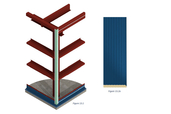
Absolutely – they require that the building be protected from the possibility of damage caused by water vapor. Since the concern is to restrict the flow of airborne moisture in relatively warm air from reaching a cooler surface to condense on, they call for something to be installed on the “warm” side to prevent that flow. For most buildings across the United States, the warm side is the interior face of the roof and walls. However, if the building is kept cold as in a refrigerated warehouse or storage building, then the warm side is likely on the exterior. The same is true in southern climates where warmer, humid air is the exterior condition and cooler interiors are common.

What is the Best Solution?

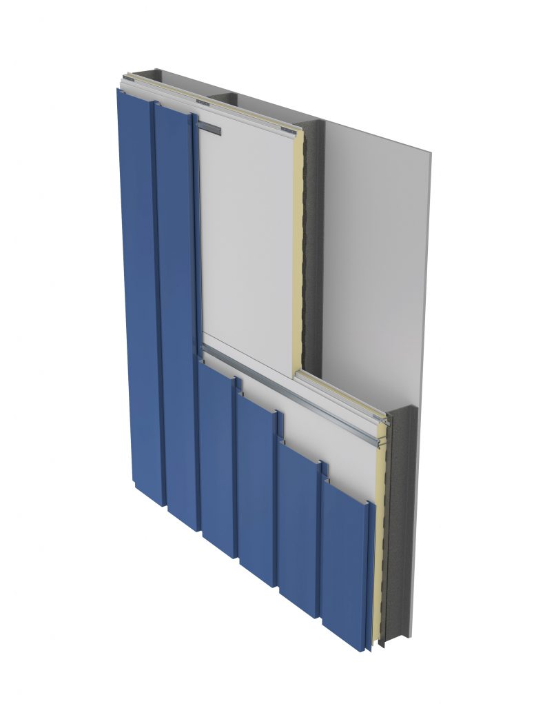
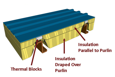
Manufacturers of insulating products have been involved in addressing the best ways to provide not only insulation to keep building temperatures warmer, but also vapor barriers to restrict the flow of airborne moisture. After literally decades of trying different types of vinyl and polyethylene facings over fiberglass insulation, most have realized that those membranes simply don’t provide enough protection to be effective. Instead, most are now offering a choice of laminated facings over the insulation that can be installed so they are exposed to the appropriate warm side of the roofing system. These fairly sophisticated laminations include:

  • Polypropylene-scrim-kraft consisting of layers of white or metalized polypropylene, fiberglass reinforcing, and white kraft paper on the order of 11-30 lb. weight
  • Polyprolene-scrim-kraft consisting of aluminum foil, fiberglass reinforcing, and 30 lb. kraft paper
  • Vinyl-reinforced polyester

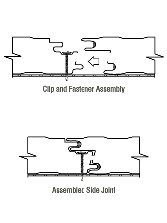
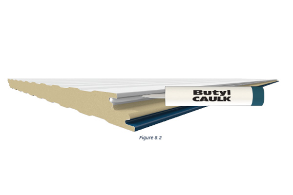
All of these latest advancements in vapor barriers can provide comparable, high levels of protection, but their selection can depend on a variety of other building factors. Therefore, it is always best to engage an architect or engineer in the design to review the needs of the entire building to select the most appropriate, specific solution for an given project. It will also be important that all seams, connections, and penetrations of the vapor barrier are addressed in the design and construction, which are similarly best addressed by an architect or engineer to assure there are no breaches in the protection provided by the barrier.

To find out more about vapor barrier and insulation products for metal roofing systems, contact your local MBCI representative.

The Importance of Vapor Seals in IMP Installations

Insulated metal panels (IMPs) used for building envelopes offer great simplicity in terms of enclosing a building in an attractive, energy-conscious manner. However, they require somewhat different thinking in terms of design and installation compared to conventional single skin panels on metal building with separately installed fiberglass insulation and vapor liners. That’s because, while the insulation aspect of IMPs is well controlled in the factory, the air and vapor sealing aspects are entirely in the hands of the installers in the field.

Why is vapor sealing a concern? Because it can make or break a building envelope. Airborne moisture that travels through seams, joints, or gaps between IMPs or between the panels and the structural steel can condense and wreak havoc on the integrity of the wall system. If that condensed moisture makes its way to unprotected edges of metal, then rusting, staining, and deterioration can occur. If it collects and drains out the bottom of the panel, then a building owner may mistakenly think that the IMPs are leaking water. If the moisture works its way inside a panel and becomes trapped it could freeze in cold climates or applications, and push panels enough to make unsightly or fail to perform as intended.

How does an installer of insulated metal panels avoid these issues? By properly using sealants as recommended by the IMP manufacturer to close the gaps and assure a vapor-tight installation. Here are the key things that installers need to pay attention to:

Sealant Types

In most cases, butyl caulking is the recommended sealant for panel joints and perimeter attachments, although urethane sealant may be called for in some cases. For fire-rated panels, silicone sealants are usually required. The important caveat for all of these sealants is that they are most successfully installed when they’ve been stored within acceptable temperature ranges. In cold weather, they may need to be kept in a warming bin; in warm weather they must be kept out of direct sunlight.

IMP
Apply continuous non-curing butyl sealant to the interior panel joint with a bead size of approximately 1/4″ as shown above.

Tools to Use

Applying any of the needed sealants will require using the proper tools. Manual caulking guns don’t provide the consistent quality of application needed, so electric or pneumatically operated applicators are required.

Sealant Location

For typical building applications (non-freezer/coolers), the vapor sealant is placed in the interior panel joints when IMPs are installed vertically. For refrigerated spaces, the sealant is commonly placed on the exterior. If the IMPs are installed horizontally, then it usually is sealed on both the interior and the exterior panel joints to help with weather sealing as well. Note that the final placement of the sealant, as well as type and location, is actually the responsibility of the mechanical contractor/architect and not the panel supplier as it is to be based also on the mechanical design of the building envelope. In addition, the entire perimeter of the panels where they meet the building structure needs to be sealed. This includes the base flashing, interior corner trim, and eave struts. Further, marriage beads of butyl sealant must be placed at all panel terminations.

IMP
Panel Installation – Sealant

Sealant Continuity

In order to be effective, all sealant and caulking must be fully continuous. That means that the thickness of the sealant bead must be consistent and thick enough to fully close all gaps between or around IMPs. It should not be overdone, however, since too much sealant will ooze out between panels that are pressed together, causing a bit of a mess on one side of the other. Sealant continuity also means that it can not be interrupted due to poor adhesion. Therefore, before any sealant is installed, the application surfaces must be cleaned and dry to be sure that full adhesion is achieved. Always check with the panel suppliers details for minimum bead size and critical locations.

Factory-Installed Option for IMP

Some IMP manufacturers offer the option of having sealant pre-installed along the edges of the IMPs. Since the panels are wrapped and sealed for shipping, the sealant is protected and should be ready for use onsite. However, in this case, it is incumbent on the installers to handle the panels quite carefully, since the inadvertent placement of a hand over the sealant can damage it or deform it enough to render it ineffective. This factory-installed option offers a labor saving in the field but must be checked during installation and can be impacted by time climate depending on the time of year. Field application, while requiring more labor, does provide greater onsite flexibility for installers. Nonetheless, in all instances, the installer must ensure the sealants are properly located.

By paying attention to the details of sealing and caulking, a metal building constructed with IMPs will be a quality installation that will hold up quite well over time. To find out more about IMP metal products and systems that can help your next building be more vapor- and weathertight, contact your local MBCI representative.

Understanding R-Values and K-Factors in Considering Thermal Resistance

Described in their most basic terms, R-value is a measure of heat resistance, while U-factor (also know as U-value) is a measure of heat transfer (heat gain or loss). The lesser known K-factor is simply the reciprocal of the R-value of the insulation divided by the thickness. What they all have in common is a relationship to the effectiveness of insulation material in resisting heat flow through a roof or wall element. There are different ways that this would be spec’d from a manufacturer to an architect or engineer. While the terminology might be familiar, the specifics are not always as clear cut as they seem. Understanding the differences will allow architects to make smart and effective choices to suit a given project’s needs.

Let’s consider some of the variables that might have an impact on what to look for and which metric to spec. As means of illustration, put yourself in the shows of a fiberglass or insulation supplier. You have a product, you know what it’s rated to, you know what the performance capability is, it’s been spec’d out to you—and you submit the bid based on those factors. But at that point you inevitably lose control over how the specs would actually get implemented. For instance, the architect may take that spec and incorporate it into a wall where it’s not used the most efficient way. This may not even be the result of a mistake; it could just be that other project elements have taken over.

Factor
Choosing the right insulation for the project can provide the building significant energy savings.

A good example would be stud walls. The fiberglass insulation supplier might indicate a given R-value, such as R-19. This would be the heat resistance value. The architect might spec and submit that bid to supply x number of square feet of that insulation based on that R-value. However, it could be cut or delivered in rolls and designed to fit between the metal studs. Metal studs are much more conductive than insulation and they provide an alternate path for the heat to flow through the assembly, almost irrespective of what the R-value and insulation is. Given these factors, the architect might have to make tradeoffs.

Choosing U-Factor

Because of all the variables encountered with R-value, U-factor is actually more recommended and reliable, and it more appropriately meets code requirements.* The concept of U-factor relates to the heat transfer coefficient but is described in the code as total heat flow per unit area through the assembly inclusive of all the short circuits as it is planned out to be built. So, an architect or engineer would know the stud spacing, the cladding material, the interior finish material and the R-value of the insulation. With that information in hand, one can go to a textbook, ASHRAE 90.1 or the ASHRAE Book of Fundamentals and find the U-factor for the assembly. It is this U-factor that is actually compared against the code requirements. It’s a better way to spec because it already takes into consideration all those things that come into play and encourages the use of suppliers (such as MBCI) that staff people who can help do those calculations or give assistance as opposed to saying, “I need R-19” and then wind up with a building that’s bridged or has more short circuits than anticipated—and having the building not perform as needed. This, in essence, is the key difference between R-value and U-factor.

A Word About K-Factor

As for K-factor, as noted this is the thickness of the insulation divided by the R-value. Its intention is to spec out an insulation when you’re not entirely sure what thickness it will be at the time you spec it out. This is fine for design-build scenarios but not a good practice for a hard bid. Bottom line: U-factor is most often the most reliable choice.

*Note: The code defines U-factor as discussed but underlying heat transfer theory may describe U-factor as 1/R-value. Insualtion suppliers might invert it and make it an R-value (but doesn’t take all the variables into consideration). Therefore, an architect would be advised to specify a “U-factor in compliance with ASHRAE, ” which includes thermal bridges, joints, etc.

Fire Resistance for Insulated Metal Panels

When it comes to understanding fire ratings for wall panels on buildings, one of the first things to overcome is incorrect information or misunderstanding that sometimes emerges around this topic. In an effort to achieve some greater clarity, let’s look at some of the basics of fire resistance ratings, particularly for insulated metal panels (IMPs).

Building Code Requirements

The fundamental reason that any wall needs to provide some degree of fire resistance is to allow people enough time to safely evacuate from a space or building in the event of a fire, or to prevent the spread of fire between defined areas or whole structures. Building and fire codes have been developed and adopted, in part, specifically to define the situations, building types, conditions and circumstances where different degrees of fire resistance are required to protect the public health, safety and welfare. Therefore, when looking at a specific building and the fire resistance ratings required, the applicable codes must be consulted and the proper determination made regarding the minimum fire resistance requirements for the different exterior and interior walls of that building.

Ratings-Based on Testing

The established means for knowing whether or not a wall meets a particular fire resistance rating is based on conducting a fire test in an independent laboratory. For IMPs, that means a manufacturer needs to submit full-size product samples to a laboratory such as Underwriter’s Laboratories (UL), which will then prepare and carry out the test according to standard, agreed-upon procedures such as ANSI/UL 263, “Standard for Fire Tests of Building Construction and Materials.” The procedures dictated by a standard such as this are intended to be the same for all similarly tested materials or products to determine the actual fire resistance rating for each. When the products are subjected to the prescribed heat and flame under uniform laboratory conditions, then they can be classified based on how well they performed. Some products, for example, may survive the test long enough to qualify for a 1- or 2-hour rating, while others may only qualify for a 30-minute rating before succumbing to the fire.

Urology Medical Office Building MBCI
The Urology Medical Office Building in Virginia Beach, Virginia utilizes 7.2 Insul-Rib® and CF Architectural – Horizontal insulated metal panels. View the product data sheets for these products for information on their fire resistance ratings.

Selecting Products

In creating or renovating a building, then, it is incumbent on the design and construction team to choose products and materials that have a proven, tested fire rating that meets or exceeds the building code requirements for the particular building at hand. If a manufacturer of IMPs has been identified ahead of time, then it may be possible to ask for evidence of the UL or similar test to prove that the selected product or assembly meets the code requirements. But many times, there is a need to first determine the requirements, and then look for the available products and manufacturers who can provide the needed fire resistance. Fortunately, UL maintains an online directory of all of the products that they have tested and certified. Their online certifications directory allows users to input selected criteria to search for specific result reports. Using this resource for IMPs, the UL Category Code of BXUV and the UL File Number of U050 should be entered to do a search. This will yield a summary list referencing the ANSU/UL263 test with a link to the BXUV.U050 test report for IMPs. There you will see under item 2: “Metal faced panels, nominal 42 in. wide by nominal 4 in. thick (for the 1 Hour Rating) nominal 7 in. thick (for the 2 Hour Rating) or nominal 8 in. thick (for the 3 hour rating) installed vertically or horizontally. Panels supplied factory double tongue and grove joint.” This lets the design and construction know that 1-, 2-, or 3-hour ratings are available depending on the thickness of the IMP and given that the factory joint is provided. Hence, the manufacturer can label their products accordingly.

By specifying and selecting the proper products that have been correctly tested and certified, then building code compliance is not only streamlined, the building will meet the inherent fire and safety requirements for the people who will occupy it.

For fire resistance information on MBCI panels, please review the product data sheets.

Beauty and Braun: The Benefits of Mixing Insulated Metal Panels with Single-Skin Panels in Commercial Design

Commercial projects aren’t one size fits all. By bringing in metal panel products to suit the individual need, designers and architects can provide custom solutions for a variety of applications. Single-skin metal panels and insulated metal panels (IMPs), if used correctly, can together add both aesthetic and functional value to your projects.

While IMPs can provide superior performance with regard to water control, air control, vapor control and thermal control, you may sometimes find your project requires—from an aesthetic perspective—the greater range of choices available in single-skin profiles. Let’s spend a little time looking at some of the reasons behind the growing trend of specifying a combination of insulated metal and single-skin panels.

Benefits of Insulated Metal Panels

Insulated metal panels are lightweight, composite exterior wall and roof panels that have metal skins and an insulating foam core. Their much-touted benefits include:

  • Superior insulating properties
  • Excellent spanning capabilities
  • Insulation and cladding all in one, which often equates to a shorter installation time and cost savings

Benefits of Single Skin

Single-skin panels, on the other hand, with their expansive array of colors, textures and profiles, may have more sophisticated aesthetics. They can be used on their own or in combination with IMPs. It should be noted, too, that single-skin panels can—in their own right (as long as the necessary insulation is incorporated) —satisfy technical and code requirements, depending on the application.

Beyond aesthetics, when it comes to design options, single-skin products offer a wide range of metal roof systems, including standing seam roof panel, curved, and even through-fastened systems. As for wall systems, those may include concealed fastened panels, interior wall and liner panels, and even canopies and soffits, not to mention exposed fastened systems. Therefore, you have a wide range of not only aesthetics options but VE (Value Engineering) options as well.

Why Mix?

So, in what situations might the designer or architect choose to combine the two panel types? Let’s examine a couple of specific scenarios related to the automotive or self-storage worlds as a means of illustration. In both of these types of applications, it is not uncommon for the designer to recognize the importance of wanting to keep the “look” of the building consistent with branding or to bring in other design elements.

Coalville Wastewater Treatment Facility
The Coalville Wastewater Treatment Facility in Logan, Utah combines the insulated CFR panel with the single-skin Artison L-12 panel.

Single-skin panels can be used as a rain screen system in the front of the building or over the office area, and would provide the greater number of design options. In the rest of the building, designers can take advantage of the strength, durability and insulation benefits of IMPs. Although you could use one or the other for these examples, the advantage of mixing the two would be achieving a certain look afforded by the profiles of single-skin, while still adhering to stringent building codes and reducing installation time—which is the practical part of using IMPs.

Focus on HPCI IMP Systems

One great example of a current trend we’re seeing at MBCI is the use of the HPCI-barrier IMP system, along with single-skin panels. The High Performance Continuous Insulation (HPCI) system is a single system that is a practical and effective replacement for the numerous barrier components found in traditional building envelopes.

HPCI Insulated Metal Panels
The HPCI Insulated Metal Panel is quick and easy to install and provides an economical solution to conventional air, water, thermal and vapor control without sacrificing thermal efficiency.

A big benefit to using the HPCI system is that the barrier wall is already in place. In terms of schedule, the HPCI barrier system is typically installed by contractors who are also installing the single-skin system, eliminating the need for multiple work crews, and thereby minimizing construction debris and reducing the likelihood of improper installation. With a general lead time of four to six weeks for the HPCI and a week or two for the single-skin, the installation goes fairly quickly. Therefore, it appeals as the best of all worlds—a single system meeting air, water, thermal and vapor codes (ex.: IBC 2016, NSTA fire standards) plus the design flexibility of a single-skin rain screen product. (Note: The HPCI panel must be separated from the interior of the building by an approved thermal barrier of 0.5″ (12.7mm) gypsum wallboard to meet IBC requirements.)

Bottom line, HPCI design features and benefits include the following:

• Provides air, water, thermal and vapor barrier in one step
• Allows you to use multiple façade options while maintaining thermal efficiency
• Easy and fast installation, with reduced construction and labor costs

Conclusion

As designers, architects and owners are getting smarter about a “fewer steps, smarter dollars” concept and an increased awareness of applicable codes and standards, not to mention lifecycle costs, the trend towards maximizing the strengths of available systems will continue to grow. Whether the right choice is an IMP system, single-skin or some combination, the possibilities are virtually endless.

Calculating Cool Roof Energy Savings

Whether it’s providing waterproofing, reducing thermal expansion and contraction, or supplying chemical and damage protection, cool metal roofing has much to offer. Of course, the most substantial benefit is the energy savings gleaned from reduced rooftop heat levels driving down air conditioning loads. In fact, the Lawrence Berkeley National Laboratory’s heat island group projects a whopping $1 billion reduction in cooling costs if cool roofs were to be implemented on a nationwide basis.

To assist architects in determining the kinds of energy savings that can be expected from cool metal roofing, the Oak Ridge National Laboratory (ORNL) has parlayed the data it gathered from a three-year evaluation of metal roofing products into a whole building energy savings calculator.

Cool metal roofs are offered in a variety of colors.
In addition to energy efficiency, cool metal roofs are known for extended durability and longevity.

Cool Roof Calculator

This calculator is called, simply enough, the Cool Roof Calculator. The easy-to-use tool is described as a quick way to compare overall energy costs and savings for a variety of roof and building conditions. Unlike some energy modeling calculators, which are limited to steep slope residential roofs with attics, ORNL’s tool models the typical low slope commercial roof with insulation placed directly over the deck and under the roofing membrane.

To calculate approximate energy savings offered by a cool metal roof, architects are instructed to input the building’s location, proposed roof R-value, roof reflectance and emittance, base energy costs, equipment efficiencies, electrical demand charges and duration.

While experts suggest that it may be difficult to accurately predict the base use and peak demand without detailed construction and cost information, tools such as the ORNL’s cool roof calculator can be a useful way to gather helpful performance estimations for a variety of building types and locations.

Attempting to do just that, the calculator outputs a number of values to offer an approximate estimate of potential energy savings, broken down into cooling energy savings—a calculation of air conditioning savings from base use and peak demand reductions—and cooling season demand savings, an estimate of the peak demand charge reduction enabled by enhanced roof reflectivity.

Accessible at http://rsc.ornl.gov, users can also compare the energy performance offered by a cool roof vs. a conventional black roof.

“It’s a nice tool to give people a feel for where a cool roof would actually help them and have the greatest impact in terms of energy use,” relates Robert A. Zabcik, PE, LEED AP BD+C, director, research and development, NCI Group Inc., Houston, in a Metal Construction News article.

Roof Reflectance Baseline

Roof reflectance and emittance, requirements and options, can be found in energy codes such as IECC, ASHRAE 90.1, California Title 24, and other local codes. Requirements may vary based on roof slope and climate zone, and may allow for either aged or initial solar reflectance, thermal emittance and/or SRI.

Fortunately, MBCI continues to stay current with individual testing and also maintains third-party tested and verified product listings through entities such as the Cool Roof Rating Council, and the U.S. EPA’s ENERGY STAR®.

3 Energy-Saving Technologies to Consider with Metal Roofs

A roof’s primary function is to keep a building weatherproof. A roof’s secondary function—and approaching nearly equal importance—is to be an energy-efficient element of the building envelope. From an energy efficiency standpoint, we’re accustomed to the inclusion of insulation. Are we as accustomed to the ideas that roof color and air leakage matter for energy efficiency? The building industry is embracing all of these technologies in an effort to save energy.  So how does an installer make it all work?

Insulation

NAIMA.org
Photo Courtesy of NAIMA

Insulation requirements for roofs on metal buildings (according to the 2015 IECC) range from R-19+R-11 LS up to R-30+R-11 LS, depending on climate zone. The first layer is draped over the purlins and requires a thermal spacer block with an R-3.5. A second layer is installed at perpendicular and is required to include a liner system (LS), which is a continuous vapor barrier installed below the purlins and is uninterrupted by framing members. The crisscrossed layers help reduce convective air movement within the insulation layer, making the insulation layer more effective. And, good news!—the vapor barrier can also be an air barrier. So, on to air barriers.

Air Barriers

Even small air leaks in buildings can account for a 30 to 40% heat loss during heating season (winter), regardless of the amount of insulation. It can’t be overstated—air barriers are critical to an energy-efficient roof and overall building envelope. The LS, or vapor barrier, can be an air barrier only if the seams of the LS are sealed to prevent air passage. The junction between the air barrier in the roof and walls is critical; it must be joined to be continuous. Often, a separate material (adhered membranes or spray-applied foams) is used as the transition from wall to roof. Or, the roof and wall air barriers might end on opposite sides of a perimeter beam or purlin, connecting the two air barriers. Also, any penetrations through the roof need to be sealed to the air barrier. Being continuous/having continuity is key to constructing a properly functioning air barrier!

Roof Color

We’ve heard a lot about roof color. Where air conditioning is prevalent (e.g., the Southwest), highly reflective roofs make sense, especially if there is minimal insulation. Where heating is prevalent, roof color becomes less effective for energy efficiency for a couple reasons. One, buildings require significant amounts of insulation, and two, there is much less direct heat gain from the sun over the course of a year. Where heating and cooling are both used regularly (e.g., Nashville, Chicago), it’s not a matter of “black or white.” There are many metal roof colors that are moderately reflective, so they balance reflectivity and heat gain as the seasons change.

Contemplate the interaction of insulation, roof color and air barriers on each metal roofing project.

Better Barriers: Meeting Thermal Performance and Controlling Air & Moisture

Panelized metal exteriors have joints. It’s just a rule of best-practice design. Yet these joints are seen by some as interruptions in the façade or roof, when in fact they are connections — the opposite, one can argue, of the word “interruption” that suggests a discontinuity.

Edie's Crossing
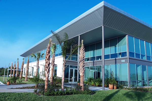
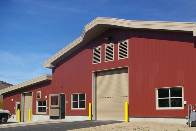
In fact, engineered metal panel systems offer arguably the best possible continuous exterior system. Not only are they properly applied exterior to the building structure—outboard of columns, joists and girts—but they are also designed to ensure an unbroken chain of thermal control and barrier protection. Combined with controlled penetration assemblies as well as windows, doors and skylights that are engineered as part of the façade and roof system, the insulated metal panel (IMP) products provide unequaled performance.

That’s the main reason that specialized facilities designed for maximum environmental barrier control are made of IMPs: refrigerated warehouses, R&D laboratories, air traffic control towers and MRI clinics, to name a few.

But any facility should benefit from the best performance possible with metal roofing and wall panels. Consider insulation shorthand for the code-mandated thermal barrier required for opaque wall areas in ASHRAE 90.1 and the International Energy Conservation Code (IECC). For a given climate zone, says Robert A. Zabcik, P.E., director of R&D with NCI Group, the project team can calculate the functional amount of insulation needed by using either the “Minimum Rated R-values” method or the “Maximum U-factor Assembly” calculation. For IMPs, teams use the Maximum U-factor Assembly, which can be tested using ASTM C1363.

With IMPs, the test shows thermal performance values up to R-8.515 and better per inch of panel thickness, meaning that a 2.5-inch-deep panel would easily meet the IECC and ASHRAE minimums.

With metal roofing panels and wall panels, a building team can achieve needed energy performance levels with this single-source enclosure, providing a continuous blanket of protection.

The same is true for air and moisture control. In a July 2015 paper by Building Science Corp., principal John Straube wrote, “Insulated metal panels can provide an exceptionally rigid, strong and air impermeable component of an air barrier system.” He noted that, “Air leakage condensation cannot occur within the body of the insulated metal panel, even if one of the metal skins is breached, because all materials are completely air impermeable and there are no voids to allow air flow.”

In terms of water control, Straube writes that IMPs have a continuous steel face that is a “high-performance, durable water control layer: water simply will not leak through steel, and cracks and holes will not form over time. The exterior location of the water barrier,” he adds, “offers some real advantages.”

Clip-Fastener-AssemblyEnfold_blog

Connecting the panels at transitions, penetrations and panel joints is the key, of course. Straube notes that sealant, sheet metal, and sheet membranes are effective and commonly used to protect joints.

In my experience, these joint details are incredibly effective. They often outlast most other components of the building. Even more important, they help make IMPs better barriers that meet thermal, air and moisture performance needs. They help make metal panels one of the best choices of all.

Sustainability Begets Resiliency…In Practice

McMahaon Centennial Complex, Cameron University

Sustainability is the buzzword started by USGBC that is pushing us to design and build environmentally friendly buildings.  And that’s a good thing.  However, from a practical—and roofing—standpoint, what we can most readily do with roofs is design them to be resilient.  Roof system resiliency is the tangible aspect of sustainability that the “regular” population can get their heads around.  Resiliency—the ability to bounce back—is understandable.

Loosely speaking, a resilient building can withstand an extreme weather event and remain habitable and useful.  It follows that a resilient roof system is one that can withstand an extreme weather event and continue to perform and provide shelter.

What makes a metal roof system resilient?  It needs to be tough and durable, wind and impact resistant, highly insulated and appropriately reflective, and perhaps be a location for energy production.

An extreme weather event typically means high winds.  A resilient metal roof system needs to withstand above-code wind events.  Remember, codes are minimum design requirements; there is nothing stopping us from designing metal panel roofs above code requirements!  If a building is located in a 120 mph wind zone, increase the design/increase the attachment as if it were in a 140 mph wind zone.  And, very importantly, increasing the wind resistance of the edge details is critical to the wind resistance of a roof system.

Toughness is important.  Increasing the thickness of a metal panel roof system increases resistance to impacts and very likely increases service life (of the metal panel, at least).  Tough and durable seams are important, too.  A double-lock standing seam is one of the best seam types for metal roofs.  A little bit of extra effort at the seam can go a long way for durability, weatherproofing, and longevity.

Highly insulated and appropriately reflective are also traits of resiliency.  High R-value means less thermal transfer across the roof assembly.  Two layers, staggered or crisscrossed, provide a thermally efficient insulation layer.  Using thermal breaks between the metal panels and the metal substructure adds to the thermal efficiency.  Reflective roofs help reduce heat transfer through the roof assembly.  The effectiveness of a roof’s color and reflectivity to save energy depends on many items, such as location, stories, and building type.

Enhanced wind resistance, improved impact resistance and toughness, high R-value, and reflectivity and color are passive design elements that increase the resiliency of a building’s rooftop.  And let’s not forget that rooftop energy production can provide electricity to critical components of a building, such as a freezer section of a grocery store.  Hurricane Sandy put resiliency on the public radar; resilient buildings are here to stay.

Find a sales representative