Project Services for Metal Buildings and Roofing: Part 2

In our last blog posting, we identified the project services that are available from MBCI and the typical process that contractors for metal buildings and roofing might experience in using them. In this posting, we will take a closer look at why so many contractors are taking advantage of these very helpful services and reaping multiple benefits.

We start by pointing out that, while it hasn’t historically been well-known that these project manager led services are available, things are changing. MBCI in particular has seen a 40 percent increase in service requests in just the past 2 years! The biggest growth has occurred in the areas of custom designs, high-end architectural buildings, and projects that use insulated metal panels (IMPs). Nonetheless, it has been recognized that virtually all types of projects benefit from these services. Therefore, it should come as no surprise that the combined MBCI project management teams are servicing 100 to 150 projects at any one time.Project Services Part 2 March 2019 Blog

While it is hard to pinpoint why this impressive growth is happening in the use of project services, there are some commonly reported advantages such as the following:

Single Point of Contact: By having a designated project manager at the manufacturing company, communication is direct and streamlined. Further, the project manager takes care of everything from start to finish in regards to the metal building or roofing package. That means the contractor is freed up to focus on the site-specific aspects of the installation without needing to worry about managing the process on the manufacturer’s end.

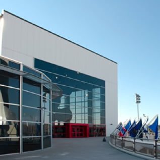
Applicability: The range of building types that have benefitted from these services is all-encompassing, indicating that these services are applicable to virtually any metal building or roofing project. Project service teams are experienced in virtually all types of non-residential construction including commercial, retail, hospitality, institutional, schools, higher education, hospitals, government buildings, and many more.

Regional Expertise: The MBCI project service teams are organized so that they can focus on one of four specific regions of the United States. That means contractors receive attention from people who understand localized concerns.

Assistance During Design: When architects and engineers need some information on using metal building or roofing systems, the project manager can, as a courtesy, assist the contractor in providing design assistance. This includes helping designers become more familiar with metal product offerings and generally to become more informed and up to date on options. There is never an intent to lead the design or move the project in any particular direction.

Price Quotes: This is often the biggest and most noted benefit of working with the project service team. By having a relationship with a manufacturer, accurate quotes can be obtained quickly to allow bid deadlines to be met with a clear understanding of scope and confidence in the numbers.

Engineered Drawings: The ability to provide complete, engineered drawings is a big advantage instead of needing to find a local engineer take on that task.

Detailed Bill of Materials: All of the take-offs and ordering are done right from the information prepared by the project services team. There is no need for the contractor to spend the time on a separate take-off.

Scheduling Flexibility: The project manager can work with the contractor and work out a production, fabrication, and delivery schedule that meets the needs of the project. For large projects, this might mean phasing delivery of different parts of the package to suit the overall project schedule. Overall, projects have been done with coordinated schedules that are as short as 2 months, or phased up to 2-1/2 years.

Full Erection Drawings: Along with the full package of building materials, a full set of erection drawings are provided that serve as a virtual “installation manual” to help streamline the work in the field.

There are certainly other reasons for using these project services, but considering that most contractors don’t have the capabilities to do all of these things in-house, it can be a real time and money saver to take advantage of them from the manufacturer. Once contractors become aware of the availability of these services and the streamlined results, they often sign up for them repeatedly.

To find out more about how to successfully take advantage of these services and work with a project manager, contact your local MBCI representative.

Project Services for Metal Buildings and Roofing: Part 1

When a metal building or metal roofing project is being developed, it all starts with a design by an architect or engineer that may be rather standard, very custom, or somewhere in between. At some point a price for the metal portion of that design is requested from the contractor (i.e. an erector or sub-contractor to a general contractor) and of course that means turning to the metal building or roofing manufacturer for help.  Toward that end, MBCI offers a complete range of project services designed to streamline everything that needs to happen next in order to genuinely make life much easier for the contractor.

Project Services Part

What are these services? Essentially, there are four:

  • Estimating and price quoting services for public or private bids
  • Engineering services for the metal building systems involved
  • Drafting services for creation of shop drawings and erection drawings
  • Overall project management of all of the above plus coordination of production, shipping, and delivery.

The key to the success of these services is the assignment of a project manager who acts as the single point of contact between the contractor and the manufacturer throughout the entire project. Having a relationship with a metal building manufacturer who can assign such a project manager right up front is a huge benefit to the contractor. Here’s how the process might work in a standard project:

Cost Quote: The project manager will use the architectural drawings (submitted by the contractor) to have the project services team generate a lump sum price. That price is limited specifically to the metal building or roofing package with a clear description of what is included and what is not. That allows the contractor to develop the remaining costs for labor and equipment to erect the metal building along with any separate project costs as appropriate.

Detailed Drawings: Assuming the contractor is selected to proceed with the work, then an agreement on full project services can be made. Based on the architectural and/or engineering drawings, the project manager will then arrange for the detailed shop drawings to be prepared (including engineering stamp or seal if needed) so they can be submitted to the architect for review and approval. Note, that this will be a requirement of the manufacturer as well since they will not do take-offs from other people’s drawings for their manufactured systems. The shop drawings will notate all of the required components necessary to install and MBCI will order plus deliver all items required upon request/approval.

Scheduling and Production: Once all of the drawings are approved, then a full production schedule can be prepared with delivery dates identified. The project manager will oversee and coordinate the various people involved to see that things are progressing as planned and intervene as needed if any changes come up from the architect, owner, contractor, or manufacturer.

Delivery and Installation: When ready, the metal building package can be prepared and delivered according to the contractor’s schedule. Full erection drawings will be included which have enough detail that they are a virtual “instruction manual” for putting the building together.

That’s the typical process. In our next blog post, we will discuss the many reasons that contractors are taking advantage of these project services to save them time, money, and hassle. In the meantime, to find out more about how to successfully work together with MBCI, contact your local MBCI representative.

Fire Resistance for Insulated Metal Panels

When it comes to understanding fire ratings for wall panels on buildings, one of the first things to overcome is incorrect information or misunderstanding that sometimes emerges around this topic. In an effort to achieve some greater clarity, let’s look at some of the basics of fire resistance ratings, particularly for insulated metal panels (IMPs).

Building Code Requirements

The fundamental reason that any wall needs to provide some degree of fire resistance is to allow people enough time to safely evacuate from a space or building in the event of a fire, or to prevent the spread of fire between defined areas or whole structures. Building and fire codes have been developed and adopted, in part, specifically to define the situations, building types, conditions and circumstances where different degrees of fire resistance are required to protect the public health, safety and welfare. Therefore, when looking at a specific building and the fire resistance ratings required, the applicable codes must be consulted and the proper determination made regarding the minimum fire resistance requirements for the different exterior and interior walls of that building.

Ratings-Based on Testing

The established means for knowing whether or not a wall meets a particular fire resistance rating is based on conducting a fire test in an independent laboratory. For IMPs, that means a manufacturer needs to submit full-size product samples to a laboratory such as Underwriter’s Laboratories (UL), which will then prepare and carry out the test according to standard, agreed-upon procedures such as ANSI/UL 263, “Standard for Fire Tests of Building Construction and Materials.” The procedures dictated by a standard such as this are intended to be the same for all similarly tested materials or products to determine the actual fire resistance rating for each. When the products are subjected to the prescribed heat and flame under uniform laboratory conditions, then they can be classified based on how well they performed. Some products, for example, may survive the test long enough to qualify for a 1- or 2-hour rating, while others may only qualify for a 30-minute rating before succumbing to the fire.

Urology Medical Office Building MBCI
The Urology Medical Office Building in Virginia Beach, Virginia utilizes 7.2 Insul-Rib® and CF Architectural – Horizontal insulated metal panels. View the product data sheets for these products for information on their fire resistance ratings.

Selecting Products

In creating or renovating a building, then, it is incumbent on the design and construction team to choose products and materials that have a proven, tested fire rating that meets or exceeds the building code requirements for the particular building at hand. If a manufacturer of IMPs has been identified ahead of time, then it may be possible to ask for evidence of the UL or similar test to prove that the selected product or assembly meets the code requirements. But many times, there is a need to first determine the requirements, and then look for the available products and manufacturers who can provide the needed fire resistance. Fortunately, UL maintains an online directory of all of the products that they have tested and certified. Their online certifications directory allows users to input selected criteria to search for specific result reports. Using this resource for IMPs, the UL Category Code of BXUV and the UL File Number of U050 should be entered to do a search. This will yield a summary list referencing the ANSU/UL263 test with a link to the BXUV.U050 test report for IMPs. There you will see under item 2: “Metal faced panels, nominal 42 in. wide by nominal 4 in. thick (for the 1 Hour Rating) nominal 7 in. thick (for the 2 Hour Rating) or nominal 8 in. thick (for the 3 hour rating) installed vertically or horizontally. Panels supplied factory double tongue and grove joint.” This lets the design and construction know that 1-, 2-, or 3-hour ratings are available depending on the thickness of the IMP and given that the factory joint is provided. Hence, the manufacturer can label their products accordingly.

By specifying and selecting the proper products that have been correctly tested and certified, then building code compliance is not only streamlined, the building will meet the inherent fire and safety requirements for the people who will occupy it.

For fire resistance information on MBCI panels, please review the product data sheets.

Selecting Metal Panels Based on Roof Slope

If you’re reading this article, then you are probably already aware that metal roofing can provide many benefits, including longevity, durability and water shedding—not to mention the aesthetic features of today’s metal roof products. When specifying a metal roof system, choosing the correct panel is a key factor. Roof slope is critical in determining that choice. Let’s take a look at some of the main things to consider when choosing a metal roof panel with regard to roof slope, including building codes, minimum slope requirements and typical applications.

Building Codes

Building codes are perhaps the most important driving force dictating the roof slope to choose. Different types of roofs have distinct specifications for installation. According to the 2012 International Building Code (1507.4.2 Deck slope), minimum slopes for roof panels need to comply with the following:

  1. The minimum slope for lapped, non-soldered seam metal roofs without applied lap sealant shall be three units vertical in 12 units horizontal (25-percent slope).
  2. The minimum slope for lapped, non-soldered seam metal roofs with applied lap sealant shall be one-half unit vertical in 12 units horizontal (4-percent slope). Lap sealants shall be applied in accordance with the approved manufacturer’s installation instructions.
  3. The minimum slope for standing seam of roof systems shall be one-quarter unit vertical in 12 units horizontal (2-percent slope).

Minimum Roof Slope Requirements

Depending on the roof profile, there are minimum roof slope requirements for each panel, which need to be considered. The profile refers to the shape the metal sheets take when they bend to form panels. Metal roof slope is expressed by a ratio indicating the roof pitch, which notes the vertical rise of the roof (in inches) for every 12 inches the roof runs horizontally—in other words, dividing the vertical rise and its horizontal span. The most common slopes are: 3:12, 1/2:12 and 1/4:12. When looking at metal roofing panel, you will need to consult with the manufacturer to ensure that the metal panel you selected will work for your application.

MBCI Roof Panels and Minimum Slopes

Applications: Low Slope or Steep Slope

Commercial Application– Low Slope Roofs

A low-slope roof is one whose slope is less than 3:12. Low slope roofs have several benefits. They have simpler geometry that is often much less expensive to construct and low slope metal roofs require fewer materials than a steep slope, which reduce material costs. Metal roofing panels are excellent solutions for roofs with low slopes. Commercial roofs are typically low slope (less than a 3:12 slope), and larger than residential roofs. This is due to low slope metal roofs being a bit easier to build on large structures.

1/2:12 Metal Roof Slope
Cecilia Junior High in Cecilia, Louisiana uses 7,180 sq. ft. of MBCI’s SuperLok®. This panel requires a minimum slope of 1/2:12.
Residential Application– Steep Slope Roofs

A steep slope roof is one whose slope is greater than 3:12. Steeper slopes are ideal for areas that have higher snow loads and will also prevent the possibility of ponding water on the roof. When it comes to residential construction, your roof is a visible part of the structure. Choosing a metal roof for residential construction involves choosing a panel profile that will be aesthetically pleasing.

Steel Slope Metal Roof
It is common to use steep slopes in residential applications, such as this home in Guntersville, Alabama that utilizes MBCI’s LokSeam® (requiring a minimum slope of 3:12).

Conclusion

Regardless of whether you’re choosing metal panels for a commercial or residential structure, slope matters. Following common standards, doing your research and paying attention to manufacturer guidelines regarding minimum slope will ensure you’re reaping the full benefit of your metal panel selection.

For More Information

To learn more about metal roof slopes, check out:

Calculating Cool Roof Energy Savings

Whether it’s providing waterproofing, reducing thermal expansion and contraction, or supplying chemical and damage protection, cool metal roofing has much to offer. Of course, the most substantial benefit is the energy savings gleaned from reduced rooftop heat levels driving down air conditioning loads. In fact, the Lawrence Berkeley National Laboratory’s heat island group projects a whopping $1 billion reduction in cooling costs if cool roofs were to be implemented on a nationwide basis.

To assist architects in determining the kinds of energy savings that can be expected from cool metal roofing, the Oak Ridge National Laboratory (ORNL) has parlayed the data it gathered from a three-year evaluation of metal roofing products into a whole building energy savings calculator.

Cool metal roofs are offered in a variety of colors.
In addition to energy efficiency, cool metal roofs are known for extended durability and longevity.

Cool Roof Calculator

This calculator is called, simply enough, the Cool Roof Calculator. The easy-to-use tool is described as a quick way to compare overall energy costs and savings for a variety of roof and building conditions. Unlike some energy modeling calculators, which are limited to steep slope residential roofs with attics, ORNL’s tool models the typical low slope commercial roof with insulation placed directly over the deck and under the roofing membrane.

To calculate approximate energy savings offered by a cool metal roof, architects are instructed to input the building’s location, proposed roof R-value, roof reflectance and emittance, base energy costs, equipment efficiencies, electrical demand charges and duration.

While experts suggest that it may be difficult to accurately predict the base use and peak demand without detailed construction and cost information, tools such as the ORNL’s cool roof calculator can be a useful way to gather helpful performance estimations for a variety of building types and locations.

Attempting to do just that, the calculator outputs a number of values to offer an approximate estimate of potential energy savings, broken down into cooling energy savings—a calculation of air conditioning savings from base use and peak demand reductions—and cooling season demand savings, an estimate of the peak demand charge reduction enabled by enhanced roof reflectivity.

Accessible at http://rsc.ornl.gov, users can also compare the energy performance offered by a cool roof vs. a conventional black roof.

“It’s a nice tool to give people a feel for where a cool roof would actually help them and have the greatest impact in terms of energy use,” relates Robert A. Zabcik, PE, LEED AP BD+C, director, research and development, NCI Group Inc., Houston, in a Metal Construction News article.

Roof Reflectance Baseline

Roof reflectance and emittance, requirements and options, can be found in energy codes such as IECC, ASHRAE 90.1, California Title 24, and other local codes. Requirements may vary based on roof slope and climate zone, and may allow for either aged or initial solar reflectance, thermal emittance and/or SRI.

Fortunately, MBCI continues to stay current with individual testing and also maintains third-party tested and verified product listings through entities such as the Cool Roof Rating Council, and the U.S. EPA’s ENERGY STAR®.

Spray Polyurethane Foam (SPF) Insulation on Metal Roof and Wall Panels

With building code compliance and sustainable building envelopes at the forefront in today’s marketplace, spray polyurethane foam insulation (SPF) applied to single skin metal roof and wall panels is an alternative to insulated metal panels with a manufacture-applied polyurethane foam core. SPF insulation improves a building’s energy efficiency and provides thermal, air and vapor barrier capabilities.

What Is Spray Polyurethane Foam (SPF) Insulation?

SPF insulation consists of isocyanate and polyol resin that is chemically combined and applied to surfaces using a spray gun. SPF insulation can be open cell or closed cell.  Open-cell foam provides insulation and air sealing for a building, but is water and vapor permeable. Closed-cell foam provides better insulation than open cell and also functions as an air barrier. Closed-cell foam differs from open cell in that it prevents water entry, minimizes moisture vapor permeability and decreases air leakage, making it the preferred insulation to apply to metal panels.

Spray Foam Insulation with Metal Panels
Spray Polyurethane Foam Insulation with Metal Panels. Image courtesy of Spray Polyurethane Foam Alliance

SPF insulation is well suited for use as interior insulation for metal wall and through-fastened metal roof panels. The traditional thermal insulation layer—one or two layers of batt insulation with a facer—has its intricacies; for example, compressed areas and difficulty taping seams at edges and penetrations for air barrier performance.  But because of SPF’s inherent physical characteristics and spray application method, SPF overcomes many obstacles.

8 Application and Safety Tips for SPF

Using SPF to fully insulate and seal a building with metal panels can have unintended consequences if the material characteristics and project parameters are not well thought out. The Metal Construction Association (MCA) recently conducted research with the Spray Polyurethane Foam Alliance (SPFA) and published their findings in a technical bulletin. It includes the following best practices and considerations for installing SPF.

Image courtesy of Spray Polyurethane Foam Alliance
  1. Utilize a certified foam spray technician to ensure the insulation meets the desired thickness, density and adhesion.
  2. Only apply SPF to clean, dry areas.
  3. SPF should not be used on standing seam metal roof panels because it may restrict the thermal movement of the panels, causing distortion.
  4. Follow a “picture frame” application technique, further detailed here, to prevent SPF from getting between girts and metal panels, causing deformation.
  5. Notify other contractors, including HVAC and electrical, to ensure necessary precautions are made.
  6. Follow building code requirements for fire protection because in some instances SPF may meet thermal barrier requirements.
  7. Prevent SPF chemicals from being drawn into a building’s ventilation system during and after installation. There may be a mandated wait time before other occupants can reenter the space.
  8. Consult with your metal panel manufacturer before applying SPF.

Read more recommendations and findings by the MCA by downloading their technical bulletin, Spray Polyurethane Foam Insulation on Interior Surfaces of Metal Panels, here.

Daylighting 101

In the age of increased energy efficiency requirements in buildings, designers often find themselves spending time and resources squeezing performance out of systems with relatively little gain in efficiency. More and more, building insulation systems seem to fall into this category. The authors of the building codes recognize this as well and have reacted by turning their focus on other metrics like air infiltration where more substantial gains are to be had. A similar situation exists with lighting efficiency. However, when it comes to daylighting, designers are often pushed out of their comfort zone because lighting concepts and terminology is quite esoteric and difficult to comprehend.

Daylighting
m
The truth is that most people take light for granted and aren’t aware of the complexity of lighting for human activity and comfort. Probably the biggest reason for this complexity is the fact that the human eye is the only way we can judge light and although the eye is an evolutionary masterpiece, it has its own idiosyncrasies and no two eyes work identically. For instance, the typical human eye can discern shades of green at much greater accuracy than other colors and because of this sensitivity, green light is often perceived as brighter than other colors at the same energy level. Therefore, quantifying light level for human comfort and function must take this sensitivity into account, leading to some complexity. Here are some basic principles that you need to understand:

A steradian is a unit of solid angle measure. You can think of a 1 steradian solid angle as a cone cut out of a sphere with the apex of the cone at the center of the sphere and cross-section angle of approximately 66 degrees. A unique property of a 1 steradian solid angle is that the area of the semispherical “cap” captured by the cone is equal to the radius of the sphere squared. This makes it a convenient shape to use in measuring the amount of light projecting from a source at the apex of the cone through its interior and onto the cap because the amount of energy passing through any cross-section along the way is always the same. There are 4π, or approximately 12, steradian in a sphere.

Surface area of the "cap" is equal to radius of the sphere squared.

Light is generated at the molecular level by the outer bands of electrons surrounding a given atom. When these electrons become excited at a high enough level, they emit a burst of energy in the form of electromagnetic radiation of a wavelength interval unique to the emitting atom in order to return to a lower energy state. If the energy level is just right, this wavelength will be in the visible light spectrum and viewed as a specific color. White light is formed when many atoms respond at various energy levels distributed across the entire visible spectrum in a pattern such that the energy transmitted is roughly constant with wavelength. The human eye is not responsive enough to discern the different colors hitting it, so an overall stimulation results in a static or “white” response. (There is a similar concept for sound as well, called “white noise”, when the ear cannot detect the individual vibration frequencies.)

The absolute brightness of light is given by the total energy it transfers through electromagnetic modulation. It is determined by summing up the energies transferred by each incorporated wavelength. As light travels from a point source, this energy spreads, causing the amount of energy arriving at a single point in space to decrease as that point is placed farther away from the light source. Brightness decreases with the square of the distance from which it is viewed. In other words, a light will appear ¼ as bright when viewed from a distance twice as far.

Because the human eye is more sensitive to green light than other colors, the brightness it perceives from different lights can only be effectively compared at the same color or wavelength. For light used for human function and comfort, it has been standardized to quantify the brightness at the 555 nanometer wavelength, which is near the center of green in the visible light spectrum, and then adjust for the effect of other colors consistent with how the human eye perceives them. Color is accounted for by weighting the energies transmitted at other wavelengths using the luminosity function. The resulting quantity is called perceived brightness. The luminosity function is similar to a bell curve and it represents how relative brightness of various colors is perceived by the typical human eye. As you might expect, the luminosity curve peaks at a wavelength near 555 nanometers.

Absolute brightness is measured in watts and should only be used when comparing lights of the same color. This should not be confused with power consumption, which is also measured in watts. Perceived brightness is instead expressed in candela and is the only way light of mixed color (on non-monochromatic) can be compared. A one candela light source with a wavelength of 555 nanometers transmits 1/683 of a watt of energy.

It is also important to be able to quantify total light output of a light source. Real-world light sources are not usually of equal brightness in all directions, so candela is not the best measurement to use. To account for spatial variation, total light output is defined as the sum total of light passing through every point in a cross-section of a one steradian solid angle, considering a light source at the apex, divided by the area of the section. This results in the same quantity regardless of the location of the cross-section. So, if a light were to transmit one candela through each point in the cross-section of a unit steradian, then it would be said to produce one lumen of light. Likewise, a 555 nanometer light source radiating one watt per steradian of energy produces 683 lumens.

Finally, the effect of light projected onto a surface must be defined, commonly called illumination level. If a light projects through a solid angle of one steradian at a uniform perceived brightness of one candela, the illumination level achieved one foot away is called a footcandle. This definition confuses many people because it is contrary to what the name might imply. But because a unit steradian is used as the basis, a footcandle equates to one lumen per square foot and it is generally much easier to think of illumination level in this way. Lux is the metric equivalent to a footcandle and there is about 10.8 lux in a footcandle. Since illumination level differences of one tenth of a footcandle are not detectable by the human eye, this is often simplified to 10 lux per footcandle.

To put this all into context, a dome skylight 24” in diameter, elevated a foot above a 30’ high roof on a 20’ x 20’ grid on an open building in El Paso, Texas, achieves about 25 footcandles at a level 4’ above the floor at noon on March 21st (typical spring equinox). Compare this versus the following recommended illumination levels for various tasks as recommended by The Whole Building Design Guide:

Whole Building Design Guide Illuminatin Levels

Understanding these concepts will help you get more out of MBCI’s latest whitepaper, Shining Light on Daylighting with Metal Roofs, where MBCI explores the subject in detail, wholly within the context of metal roofs and metal wall systems. We hope you find it…err, enlightening.

Download the White Paper, Daylighting with Metal Roofs

Wind Designs for Metal Roofs

One of the most important requirements for metal roof installation is ensuring that a roof stays in place when the wind blows.  The core concept is that the roof’s wind resistance needs to be greater than the wind loads acting on a building’s roof.  Wind resistance is most commonly determined by a physical test; wind loads are calculated.

Calculating Wind Loads

Wind loads are based on the design wind speed (which is based on the geographic location of the building), height of the roof, exposure category, roof type, enclosure classification and risk category.  The height of the roof, and exposure and risk categories are factors that are used to convert design wind speed to an uplift pressure.  Wind speed maps and the rules to calculate wind pressures are found in Section 1609, Wind Loads, in the 2012 or 2015 IBC.  The information is based on an engineering standard written by The American Society of Civil Engineers, “ASCE 7-10, Minimum Design Loads for Buildings and Other Structures.”Wind Uplift Testing_2

Defining Exposure Risk Category

Exposure categories relate to the characteristics of the ground, such as urban and suburban areas or open terrain with some obstructions or flat areas like open water.  There are 4 risk categories.  Category I is low risk to humans, such as agricultural facilities. Category III includes, for example, buildings for public assembly, colleges and universities, and water treatment facilities.  Category IV includes essential facilities like hospitals and police stations.  Category II is everything else—most roofs are Category II. A building shall be classified as enclosed, open or partially enclosed. The enclosure classification is used to determine the internal pressure coefficients used to calculate design roof pressures.

Determining Wind Pressures

Contractors should work with a structural engineer or the metal panel manufacturer to determine the wind pressures for each roofing project.  Wind pressures are determined for the field of the roof, the perimeters and the corners, where loads are largest.  Only after determining the design pressures can the appropriate metal panel roof system and attachment requirements be designed.

Testing Uplift Resistance

Physical tests are the most common method to determine uplift resistance.  Panel width and profile, metal type and thickness, clip type and frequency, type and number of fasteners, and the roof deck contribute to the uplift resistance of every metal panel roof system.  Metal panel roof systems installed over solid substrates (with concealed clips or through-fastened) can be designed using the following test standards: FM 4471, ASTM E 1592, UL 580, or UL 1897.  Metal panels installed over open framing can be designed using either ASTM E 1592 or FM 4471.  Manufacturers run these tests; uplift resistance data is available for most metal panel roof systems.  Installers can get this data directly from manufacturers or from web-based listing services provided by FM and UL.

Designing a Legal Metal Roof System

Wind loads and wind resistance information is necessary to verify code compliance.  Get it for every project you install!  Using systems that not only have been tested to the correct tests, but using systems that have uplift resistance greater than the design loads is key to a successful installation, and quite frankly, key to installing legal roof systems.

Roofing Underlayment and Its Attachment Requirements

The International Residential Code (IRC) is commonly considered to be a prescriptive code, which means there are many requirements included that provide specific directions. Prescriptive-based code language provides a simpler method of enforcement for inspectors. And shouldn’t that be the case for one- and two-family dwellings, where well built and affordable is the goal?

Underlayment Requirements

In Chapter 9 of the 2015 IRC, the underlayment requirements for steep-slope roof coverings are included in three tables—material types, application and attachment requirements. Each table includes specific information for metal panels and separates out high-wind areas (defined as greater than 140 mph, and is only in the southernmost portion of Florida).

Roofing underlayment by our sister company ABC.

Material Type Requirements

Underlayment types for metal panels needs to only comply with manufacturer instructions. D226 and D4869 underlayments are viable options, as long as metal panel manufacturers allow them. And very importantly for metal panels, synthetic- / polymer-based underlayments are a viable option, again, as long as the panel manufacturer allows them to be used.

For metal panels in high wind areas, only D226 Type II and D4869 Type IV are allowed. In other words, only the heaviest materials are allowed in the highest wind zones.

Application Requirements

Simply put, underlayment should be applied according to the manufacturer’s installation instructions. For high-wind areas, specific application requirements are provided:

“For roof slopes from two units vertical in 12 units horizontal (2:12), up to four units vertical in 12 units horizontal (4:12), underlayment shall be two layers applied in the following manner: apply a 19-inch strip of underlayment felt parallel to and starting at the eaves. Starting at the eave, apply 36-inch-wide sheets of underlayment, overlapping successive sheets 19 inches, and fastened sufficiently to hold in place. For roof slopes of four units vertical in 12 units horizontal (4:12) or greater, underlayment shall be one layer applied in the following manner: underlayment shall be applied shingle fashion, parallel to and starting from the eave and lapped 4 inches. End laps shall be 4 inches and shall be offset by 6 feet.”

Underlayment Attachment Requirements

Underlayment should be attached according to the manufacturer’s installation instructions. For high-wind areas, specific attachment requirements are provided:

“The underlayment shall be attached with corrosion-resistant fasteners in a grid pattern of 12 inches between side laps with a 6-inch spacing at the side laps. Underlayment shall be attached using metal or plastic cap nails or cap staples with a nominal cap diameter of not less than 1 inch. Metal caps shall have a thickness of at least 32-gage sheet metal. Power-driven metal caps shall have a minimum thickness of 0.010 inch. Minimum thickness of the outside edge of plastic caps shall be 0.035 inch. The cap nail shank shall be not less than 0.083 inch for ring shank cap nails and 0.091 inch for smooth shank cap nails. Staples shall be not less than 21 gage. Cap nail shank and cap staple legs shall have a length sufficient to penetrate through the roof sheathing or not less than 3/4 inch into the roof sheathing.”

Self-Adhesive Underlayment Options

Of course, there are exceptions to these requirements. The first is to use a self-adhesive underlayment (i.e., ice dam protection) over the entire roof. The material needs to comply with ASTM D1970, “Standard Specification for Self-Adhering Polymer Modified Bituminous Sheet Materials Used as Steep Roofing Underlayment for Ice Dam Protection” and be installed per the metal panel manufacturer’s requirements. The code also points out that roof ventilation must be considered because a self-adhesive sheet is most often an air barrier and a vapor retarder. Concerns with moisture are quite relevant when these types of materials are installed over the entire roof deck. The second exception is to tape the seams of the roof deck with 4-inch wide strips of D1970 material, and then cover the deck with underlayment. The second exception is not widely used, except when trying to reduce, or eliminate, air flow through the deck while allowing moisture to escape.

IRC Requirements for Attaching Metal Panels

The IRC also includes some, but not many, requirements for the attachment of metal panels. The IRC requires metal panels be attached per manufacturer’s installation instruction and “be secured to the supports.” This implies fasteners should be attached to purlins or rafters, but one could easily argue the roof deck is the support for the metal panels. However, the IRC does provide specifics for fasteners used to attach metal panels, but the following is only applicable if manufacturer’s instructions don’t include fastener requirements. The IRC states:

“In the absence of manufacturer’s installation instructions, the following fasteners shall be used:

  1. Galvanized fasteners shall be used for steel roofs.

  2. Copper, brass, bronze, copper alloy and 300-series stainless steel fasteners shall be used for copper roofs.

  3. Stainless steel fasteners are acceptable for metal roofs.”

The Importance of Following IRC and Manufacturer Instructions

The IRC is a prescriptive code and there are many specific requirements for underlayment and metal panels. But because of the wide variety of styles, the IRC appropriately requires installation according to manufacturer’s instructions. It’s important to specify a new roof using both manufacturers’ instructions and IRC’s specific requirements. And, remember, a metal roof will have a long service life, so the underlayment’s service life should equal that of the metal roof. Don’t be shortsighted when designing for longevity.

3 Energy-Saving Technologies to Consider with Metal Roofs

A roof’s primary function is to keep a building weatherproof. A roof’s secondary function—and approaching nearly equal importance—is to be an energy-efficient element of the building envelope. From an energy efficiency standpoint, we’re accustomed to the inclusion of insulation. Are we as accustomed to the ideas that roof color and air leakage matter for energy efficiency? The building industry is embracing all of these technologies in an effort to save energy.  So how does an installer make it all work?

Insulation

NAIMA.org
Photo Courtesy of NAIMA

Insulation requirements for roofs on metal buildings (according to the 2015 IECC) range from R-19+R-11 LS up to R-30+R-11 LS, depending on climate zone. The first layer is draped over the purlins and requires a thermal spacer block with an R-3.5. A second layer is installed at perpendicular and is required to include a liner system (LS), which is a continuous vapor barrier installed below the purlins and is uninterrupted by framing members. The crisscrossed layers help reduce convective air movement within the insulation layer, making the insulation layer more effective. And, good news!—the vapor barrier can also be an air barrier. So, on to air barriers.

Air Barriers

Even small air leaks in buildings can account for a 30 to 40% heat loss during heating season (winter), regardless of the amount of insulation. It can’t be overstated—air barriers are critical to an energy-efficient roof and overall building envelope. The LS, or vapor barrier, can be an air barrier only if the seams of the LS are sealed to prevent air passage. The junction between the air barrier in the roof and walls is critical; it must be joined to be continuous. Often, a separate material (adhered membranes or spray-applied foams) is used as the transition from wall to roof. Or, the roof and wall air barriers might end on opposite sides of a perimeter beam or purlin, connecting the two air barriers. Also, any penetrations through the roof need to be sealed to the air barrier. Being continuous/having continuity is key to constructing a properly functioning air barrier!

Roof Color

We’ve heard a lot about roof color. Where air conditioning is prevalent (e.g., the Southwest), highly reflective roofs make sense, especially if there is minimal insulation. Where heating is prevalent, roof color becomes less effective for energy efficiency for a couple reasons. One, buildings require significant amounts of insulation, and two, there is much less direct heat gain from the sun over the course of a year. Where heating and cooling are both used regularly (e.g., Nashville, Chicago), it’s not a matter of “black or white.” There are many metal roof colors that are moderately reflective, so they balance reflectivity and heat gain as the seasons change.

Contemplate the interaction of insulation, roof color and air barriers on each metal roofing project.

Find a sales representative