Did you know that roof failures are the largest hurricane loss due to wind and water damage? Metal roofing is highly recommended for the locations that deal with hurricanes and high force winds as well as other weather conditions including hail, fire and ice. Metal roof panels from MBCI are designed to meet the unique needs of Florida home and business owners.
Able to resist and withstand the extreme environmental conditions that Florida is known for, MBCI’s metal wall panels and roofing systems offer better long-term cost benefits and lasting up to three times longer than asphalt shingles. With Miami-Dade County’s strict product approval and testing processes in place, you can have peace of mind that metal panels from MBCI meet requirements.
MBCI’s standing seam metal roof systems are one of the most durable and weathertight roof systems available in the industry.
Miami-Dade County Approvals
In order for your metal panels to be compliant for structures in Miami-Dade County, all panels for both roof and walls are tested to specific test standards. In addition to submitting an application, test reports are also required to move forward with the approval process. Third-party testing is required for verification.
Metal Building Panel Approval Process
Prior to submitting a metal building for approval, multiple steps must be taken to configure and test your panels. Each unique panel configuration requires its own testing.
Approval for a product is based on one profile, one gauge and several spans. The design pressures can be used in the field, corners and perimeters or interior and end zones. If a panel manufacturer offers the same panel profile in a thicker gauge, that material can be included in the approval, but they will be limited to the design pressure of the thinner gauge. Three samples of each configuration must be tested and differ no more than 20% when results are determined. The end goal of testing is to determine design loads for the panel system at a specific span.
There are separate requirements for the testing and approval of structural steel members and frames.
Why Install MBCI Metal Panels
UL 580 Class 90 Wind Uplift Resistance
Designed for Florida
UL Class 4 Hail Impact Resistant
Class A Fire Ratings
ENERGY STAR® Certified Colors
Miami-Dade County Approved
Insurance Discounts Available
Miami-Dade County Approved Panels
Florida has implemented stricter building codes to help prevent hurricanes and wind loss. Some of the toughest codes include Miami-Dade County and Florida Building Code. MBCI offers a wide selection of products that surpass the necessary ratings. Our Miami-Dade approved panels include PBR, 5V Crimp, Craftsman™ Series – Small Batten, DoubleLok®, CFR and most insulated metal panels. For more information on MBCI’s metal roofing and wall products, speak to your sales representative or visit our website at MBCI.com.
Sloped, standing seam, metal roofing provides a continuous surface that is designed to shed water efficiently while providing a long-lasting and great looking roofing solution. When the roof design and shape is simple, (i.e. continuously extending from ridge to eaves with no changes or interruptions) then all of the attributes of the metal roofing can be assured by using some very conventional and well-known details for design and construction. But in the real world, there are lots of conditions that require more specialized attention to detail. For our purposes here, we will simply refer to those as “specialty roof conditions.”
What types of roofing conditions warrant the special attention? Most are associated with changes in the shape or surface of the roof, say where the ridge line is interrupted or offset. Others could be a means to accommodate a roof feature such as a dormer, a dutch hip type of roof, or the intersection between a ridge and a parapet wall. Some might be related to the design of a valley, particular if it is a “dead valley” that doesn’t drain directly to the gutter but stops short, as around a dormer or elsewhere. Or some could be the result of some special conditions created by the roof design such as cascading water over an edge or heavy snow accumulation conditions. There are certainly many others too, but the point is that any of them are a potential source of water leakage and building damage if they are not properly addressed.
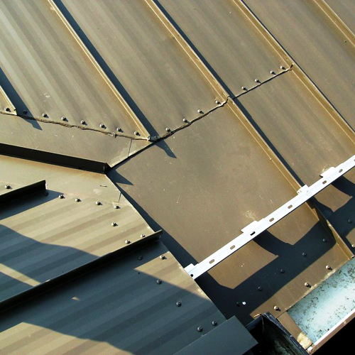
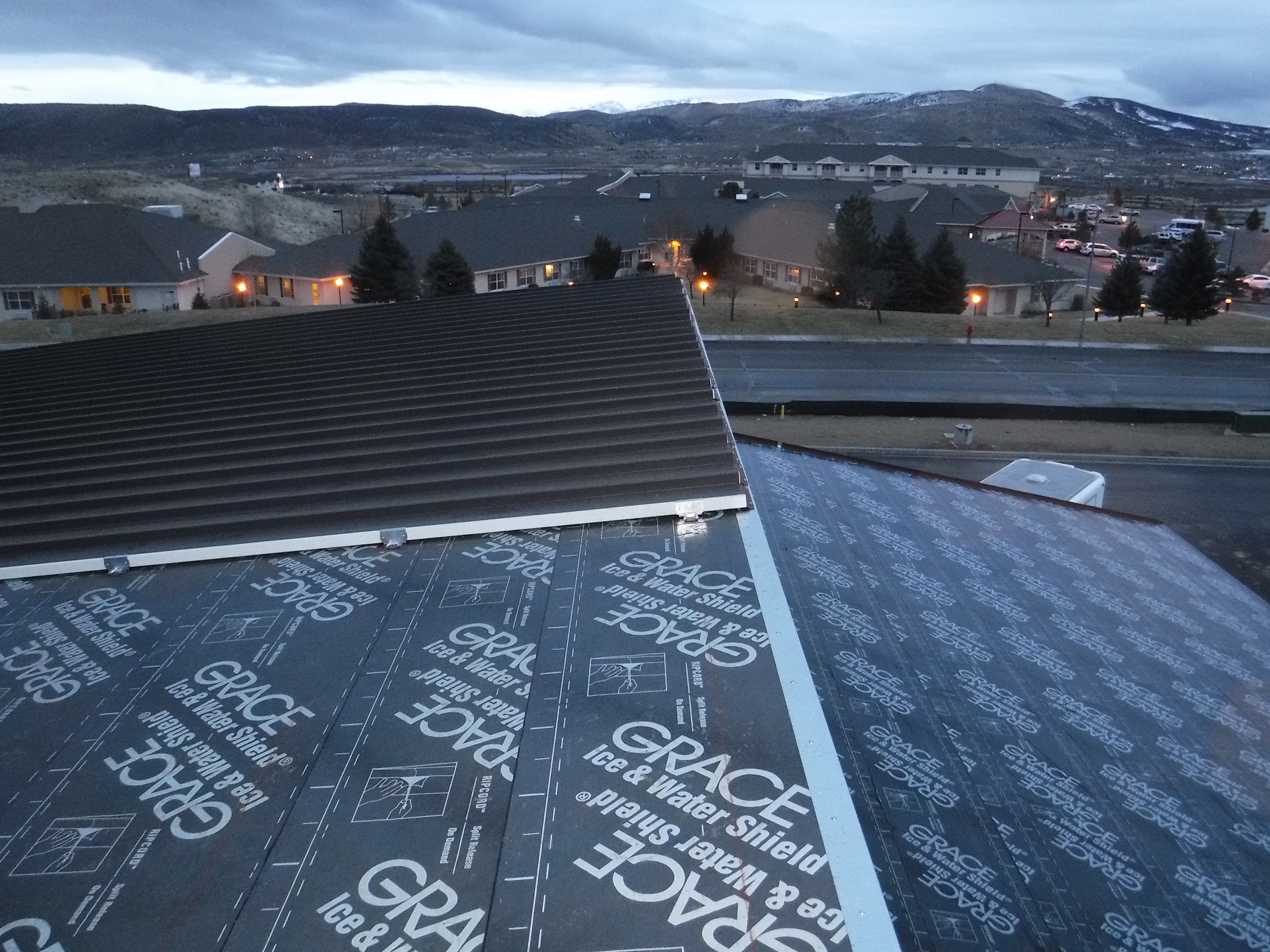
Above is an example of a special roof transition created by MBCI.
Most metal building manufacturers not only recognize the importance of such specialty roof conditions, but they also have lots of experience in developing very workable solutions for them. The key for success is found in the fundamental principles of properly overlapping (i.e. “shingling”) all materials to allow water to drain smoothly away where it is intended without getting diverted to places where it shouldn’t go. That means the metal roofing panels need to be cut, fit, and installed properly, but it also means that flashing, sealants, and fasteners need to be installed correctly too, all regardless of the slope of the roof. To communicate ways to achieve better results in the field for specialty roof conditions, manufacturers like MBCI make step-by-step details available for installers. The significance of using and following these details can not be overstated since they are a key component in getting a weathertightness warranty from the manufacturer.
As an example of how this might play out on a specific building, let’s look at a dead valley that occurs because a gable roofed dormer is installed in the main area of a roof. The first thing to recognize is that multiple layers of materials are involved in the transition around the dormer, all of which need to be installed in the proper location, following the proper sequence, and with the proper connections. A step-by-step process as detailed by the manufacturer might look like this:
Step 1:
With the substrate in place (rigid insulation over a metal deck), a special width panel will likely need to be installed and serve as the collection area for the dead valley to drain into. Then, plywood spacers and nailers are installed, and the main lower valley area is covered with “rubber” (EPDM) flashing.
Step 2:
Secure continuous eave trim over the plywood nailers and add and offset cleat on top to receive roof panels, all secured with tri-bead tape sealer and fasteners as shown.
Step 3:
Install extended valley trim across the valley with an offset cleat on either side secured as shown.
Step 4:
With all of the prior steps in place, then the installation of upper panels can begin to interface with the edge of the dead valley.
Step 5:
Continue cutting and installing panels to fit over and drain into the dead valley, which then drains without interruption onto the special width panel and the roof.
By following step by step details from the manufacturer for this or other specialty roof conditions, then the likelihood increases that everyone involved in the project is both proud and satisfied with the end results. The key is to start at the beginning with the proper planning and preparation by communicating with the manufacturer about all roof conditions that require special attention like this example.
Energy codes and increasing energy costs have prompted the installation of more roof insulation into metal buildings in recent years to make them more energy efficient. That is fundamentally a good thing and metal building manufacturers have developed ways to accommodate a variety of building enclosure packages that increase energy performance while still being engineered to meet the structural requirements of the building. This allows the whole building envelope to be designed and fabricated so it works as a complete, coordinated system.
Insulation helps maintain a comfortable interior temperature in your metal building during the winter and summer months.
The metal roofing or metal building suppliers typically don’t design the insulation systems. However, it is important to include them in the discussions or make them aware of what type of system is to be installed. It is not uncommon for a metal building to be ordered with the design stipulation of “insulation by others.” In that case, coordination is needed between the person ordering/designing the insulation system and the metal building manufacturer or roofing supplier. Since there are a great many variables in the way that insulation can be provided, it is not appropriate to think that the design of structural systems (purlins and roof bracing) and cladding systems (clips, fasteners, and metal roofing profiles) will necessarily accommodate all the same insulation in all conditions. Rather, unless the specific details of the insulation system being used in the building are communicated effectively at the time of the order, the manufacturer can not assure compatibility of the systems used with the insulation system that is to be installed.
In order to understand some of the variability in the options, let’s look at some of the common ways that metal buildings are or are not insulated.
Uninsulated Roofs:
Buildings that do not have any heat or air conditioning in them may not need for an insulated roof. This could be true for outdoor shelters, some agricultural buildings, or vehicle storage buildings. However, uninsulated metal roofs have the potential for “roof rumble” as they move due to thermal expansion and contraction, wind, or weather as there is no insulation to mask or deaden this noise. Absence of insulation can also lead to condensation during certain times of the year if temporary heat is added to the building. This condensation builds up and can drop or fall onto whatever is below. Many times condensation issues are mistaken for roof leaks when in fact it’s a mechanical design issue of the building envelope that’s not been properly addressed. If neither sound nor potential condensation are a concern, then there’s no problem. But if either or both need to be avoided, then some basic level of insulation may be prudent.
Over the Purlin Systems:
One of the most common insulation systems for metal buildings and/or open framing systems is to simply install rolls of blanket insulation. In this case, fiberglass insulation with a reinforced liner is draped over structural beams and purlins. The rolls are supplied to length by the insulation supplier based upon the roof structural layout and the required “R” value necessary for the building envelope in thicknesses that can vary from 3″ to 12″. Is is this thickness to be installed over open framing that the metal building/roofing supplier must be made aware of. Based on this thickness, the panel profile can be verified to determine if it can be used as well as confirmation of the correct clip heights and screw lengths for installation. Keep in mind that the supplier will offer a guide to the installer based upon insulation thickness. As insulation can vary by manufacturer, it will be up to the installer to make adjustments as needed in the field to ensure proper placement and hold modularity of the steel system. (See Respect the Module: Metal Roofing Panels are Modular for Good Reason)
Cavity Fill Insulation Systems:
When higher “R” values are required for roof insulation, a single layer over the open framing system may not be sufficient. When that occurs, the designers of the building envelope may need to employ the framing cavity to add more insulation. There are also variation on the cavity fill approach.
One means is to simply introduce a second layer of unfaced blanket on top of the faced insulation. Sometimes referred to as a “sag and bag” approach, here the first layer of insulation over the purlins is ordered to accommodate larger amounts of drape between the roof structure to permit another layer of unfaced insulation to be added on top. This increases the insulation thickness between the purlins but keeps it thin enough to be compressed to accommodate the roof panel installation. For coordination purposes, the thickness of this upper insulation over the purlins needs to be known by the building manufacturer so the clips and fasteners can be properly sized. Likewise, the amount of insulation draping between the purlins needs to be known to determine if purling bracing or other accessories may potentially interfere with the insulation installation.
Other types of cavity fill system may include a faced batt or face roll insulation with long tabs, which are secured to the tops of roof purlins and nest fully into the purlin cavity to fill the space more effectively. This helps in eliminating greater compression of multiple layers of insulation on top of the purlins and permits an additional layer of unfaced insulation on top of the roof structures and/or a thermal spacer block. This system may also require some intermediate banding to support the insulation between the primary supports.
A liner system may be installed that employs a continuous vapor retardent material. This liner is secured to the bottom of the roof structure and additionally supported with metal banding allowing the cavity to then be filled with unfaced insulation between the purlins. More unfaced insulation can also be added on top of the purlins as well. In all of the cases where cavity fill systems are used, it is important to advise the building manufacturer/roof supplier which type is being used to ensure proper panel clip heights and screw lengths. This is important because these systems can and will interfere with the roof structural bracing making them more difficult to install. The metal building supplier may be able to offer bracing alternatives or remedies to eliminate some or all of the bracing that would otherwise be in the way when installing the roof insulation. There may also be suggestions on how to avoid impeding or penetrating the vapor barriers which could lead to condensation issues. Overall, it is best to discuss and coordinate all of these items ahead of time.
Rigid Board/ Composite Systems:
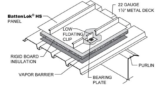
In this insulation approach, rigid foam insulation board is used to achieve the sought after energy performance. Commonly, these use metal deck panels over the roof structure thus supporting the insulation and a vapor retardant material on top of the deck. The insulation and the metal roofing can then be secured to the framing substructure or to the metal deck itself, which means the details of attachment need to be reviewed and engineered to avoid adverse affects on the roofing system.
Minimum decking gauge, clips spacing and clip screw lengths should be considered as well as associated adjustments to labor costs.
Spray-on Insulation:
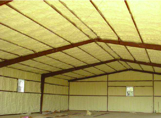
All of the above systems typically require attention to providing additional air and vapor barriers and proper cutting and fitting during installation so as not to cause unwanted infiltration or to prevent condensation from occurring. For these reasons and more, some people will consider the use of closed cell spray-on foam insulation, which can continuously provide all of these features in one product. It can also be installed after the roof is completed and structure is weathertight.
Any corrosion of the panel due to adhesion of the insulation is not covered by the panel.
In the case of metal buildings, spray-on insulation is typically applied in the field onto the inside face of installed roof panels and sometimes wall panels too. There are, however, a few concerns with this approach in metal buildings. First, if conditions are not right and the panels are not properly prepared, then the spray foam can, in fact, trap moisture between the insulation and the metal components it is sprayed onto. That can lead to corrosion of the metal or deterioration of the insulation. Secondly, not all spray foams on the market are intended for this type of use so they don’t always adhere well to some metal panels, meaning it could become loose and fall away. Finally, continuous spray foam in this application will not always be able to expand and contract at the same rate that metal does. In some cases, that could mean that the foam suffers from differential movement causing it to break or lose adhesion.
For all of these reasons, be certain to research all options before considering or selecting a foam spray-on insulation that will not negatively impact your roof performance. If a foam insulation is preferred, it may be worth considering the use of insulated metal panels (IMPs) that are designed, engineered, and fabricated to be compatible with metal building construction.
Recognizing all of the above variations and options, the key point to remember about insulating metal buildings is the importance of communication between those designing and ordering an insulated metal building and those who are manufacturing and fabricating it. To find out more about the best ways to do that, contact your local MBCI representative.
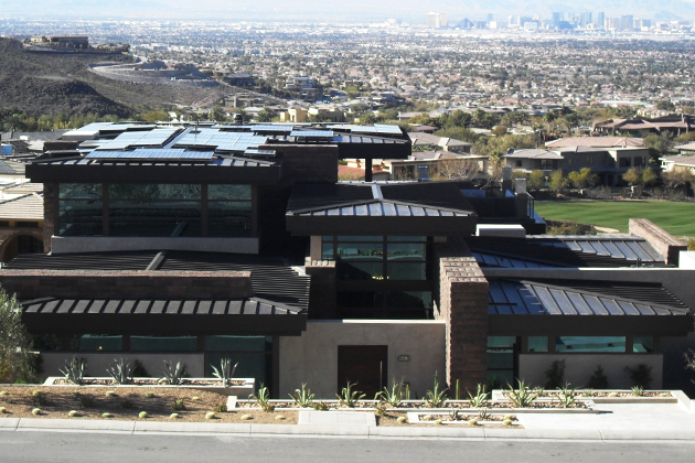
The National Association of Home Builders’ (NAHB) came to MBCI to assist in the construction of The New American Home®, a concept series built to demonstrate innovation and best practices in energy efficiency and green building construction techniques. This year, The New American Home® was built at the foot of Nevada’s Sloan Canyon where it faced harsh desert conditions.
The Problem: High Temperatures & UV Rays
There are many design and performance concerns when selecting a roofing product, particularly in areas exposed to high temperatures and prolonged exposure to sun and ultraviolet (UV) rays. One of the biggest challenges in this project was ensuring that the roof would be protected from the harmful effects of corrosion, temperature, and color fading. The building components chosen had to stand up to these conditions and maintain their appearance for years to come.
MBCI’s Metal Panel Solution
MBCI’s Craftsman™ Series High Batten and Artisan® Series L10 metal panels were selected for use as the roof solution, while Artisan® Series panels are used for the soffit and interior liners. These metal panels are finished in a Signature® 300 Midnight Bronze which complemented the beautiful scenery of Henderson, Nevada, while also providing a 40-year paint warranty to protect panels from the damage of the sun and harsh heat.
The New American Home® was built to inspire architects, home builders and others in the building industry.
The Result: Highest Level of Green Building Achievement
Using MBCI’s metal panels, The New American Home® achieved Emerald status – which is the highest levels of green building achievement recognized by the ICC 700 National Green Building Standard. Many other features made this achievement possible; solar panels, tankless water heaters, hydronic air handlers, intelligent fireplaces, sustainable buildings materials and a weather-sensitive irrigation system also added to the sustainability of the home.
Performance-based building product testing and accreditation is a critical piece of just about every aspect of construction—affecting everyone from the manufacturer to the installer and ultimately to the owner and occupant. These certifications ensure real-world property loss will be prevented and provides protection when certified products are installed correctly.
With roofing being such a vital part of any building project, roofing manufacturers must take certifications for roofing products (in this case, metal roofing products) very seriously. Below, we’ll give a brief overview of the main certifications that we—and other metal roofing companies—test to and are audited for in order for the overseeing bodies to confirm that we’re producing what we’re testing it to. In the simplest terms, these specifications, such as UL or FM, will give the contractor peace of mind that he or she can provide what is spec’d.
At MBCI, we have several certifications through which we have ratings. These include:
1. UL (Underwriters Laboratories).
UL certifies roofing materials and roof assemblies for fire performance, hail resistance and/or resistance to wind uplift. Roof deck assemblies are investigated for performance under internal fire exposures and for uplift resistance. MBCI does a good deal of testing and we have UL constructions for many of our roofing products. We get the UL construction number, impact ratings and fire ratings. UL does quarterly audits in the manufacturing areas to make sure that we’re producing the panels the way we test.
2. IAS (International Accreditation Service) certification.
IAS accreditation programs are based on recognized national and international standards that ensure acceptance of its accreditations. To meet this standard, MBCI is “Part B” of the process, as we are responsible for the components. The auditor comes in to certify that we do what we say we do. Once IAS accreditation requirements are met, the company receives a certificate of accreditation.
3. FM (Factory Mutual) approvals.
MBCI has three roofing products that are FM approved for wind uplift standards, hail resistance, internal and external fire ratings. For each, we test the product and FM comes out yearly to do an audit.
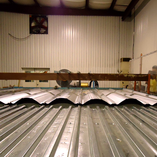
This is an example of FM wind uplift testing.
4. Dade County roofing product approvals.
Miami-Dade and Broward Counties are classified as High Velocity Hurricane Zones (HVHZ), which are rated as 150 mph plus winds. It is Florida’s highest rating. An updated testing approval process has been instituted for building products and materials used in these counties. The purpose is to mitigate damage caused by wind-borne debris resulting from hurricane-force winds. MBCI does testing and this stringent certification is applicable for anything that ships into Dade County or Broward County in Florida. Product Notice of Acceptance can be located on the Miami-Dade website for roof and wall panel systems that are Dade County approved.
Safety and performance are the most important goals. All in all, these certifications ensure that we, the manufacturer, are doing our job and that customers are getting everything they’re paying for. For more information on MBCI’s product testing, please contact a sales representative.
One of the most misunderstood aspects of a metal roofing system is the proper use of a vapor barrier. There are many sources of information about this topic – some of which are based on science, some based on anecdotal field experience, and some based on journalism. Here, we will try to break it down to the basic principles that can be used to understand the latest options for a metal building roof system today.
What is Vapor?
The observed science tells us that water can take three forms, depending on temperature and its ability to interact with other things around it. Water can be a liquid that we drink, solid ice that we can skate on, or a gaseous vapor that is part of the makeup of the air we breathe. We can’t see water vapor in the air but we can feel it – we call that humidity. High humidity means a lot of water vapor is in the air, typically coupled with higher air temperature – and both can make us feel uncomfortable and “sticky.” Low humidity means the air is dryer – more typical in lower-temperature air – but this may also be uncomfortable for our breathing, skin dryness, etc.
Why is Vapor a Concern?
As long as the gaseous water vapor stays in the air at a moderate or comfortable level, there is no real concern. However, since water vapor responds quickly to temperature, it can turn back into water as soon as it encounters a surface that is cold enough for it to make the transformation. We know this phenomenon as condensation, and anyone who has seen a cold drink collect water on the outside of a glass on a humid summer’s day has experienced it. It is the same phenomenon that shows up on the surface of windows in a building when there is a big difference between inside and outside temperatures. We know that the amount of water vapor (i.e., humidity) present and the air temperature can both be variable at any given time, but there is always a predictable point at which water vapor will condense and form water drops – this is called the dew point. When vapor in the air encounters a temperature at or below the dew point, condensation occurs.
What Does This Have to do With Metal Roofing?
Metal roofing systems and condensed moisture are not a good combination. If airborne moisture seeps into a metal roof assembly, finds a cool surface, and condenses on any surface there, it likely won’t be visible from inside or outside of the building. That trapped water can then cause rust and corrosion of metal parts, resulting in real damage. It can also collect and saturate building insulation, rendering it ineffective. If enough water condenses, it can cause visible staining or grow mold, causing concerns for people inside the building.
Vapor barriers are used in metal buildings to reduce the rate at which vapor can move through a material.
Do Building Codes Address This?
Absolutely – they require that the building be protected from the possibility of damage caused by water vapor. Since the concern is to restrict the flow of airborne moisture in relatively warm air from reaching a cooler surface to condense on, they call for something to be installed on the “warm” side to prevent that flow. For most buildings across the United States, the warm side is the interior face of the roof and walls. However, if the building is kept cold as in a refrigerated warehouse or storage building, then the warm side is likely on the exterior. The same is true in southern climates where warmer, humid air is the exterior condition and cooler interiors are common.
What is the Best Solution?
Manufacturers of insulating products have been involved in addressing the best ways to provide not only insulation to keep building temperatures warmer, but also vapor barriers to restrict the flow of airborne moisture. After literally decades of trying different types of vinyl and polyethylene facings over fiberglass insulation, most have realized that those membranes simply don’t provide enough protection to be effective. Instead, most are now offering a choice of laminated facings over the insulation that can be installed so they are exposed to the appropriate warm side of the roofing system. These fairly sophisticated laminations include:
Polypropylene-scrim-kraft consisting of layers of white or metalized polypropylene, fiberglass reinforcing, and white kraft paper on the order of 11-30 lb. weight
Polyprolene-scrim-kraft consisting of aluminum foil, fiberglass reinforcing, and 30 lb. kraft paper
Vinyl-reinforced polyester
All of these latest advancements in vapor barriers can provide comparable, high levels of protection, but their selection can depend on a variety of other building factors. Therefore, it is always best to engage an architect or engineer in the design to review the needs of the entire building to select the most appropriate, specific solution for an given project. It will also be important that all seams, connections, and penetrations of the vapor barrier are addressed in the design and construction, which are similarly best addressed by an architect or engineer to assure there are no breaches in the protection provided by the barrier.
Metal roofing is commonly installed on residential or light commercial buildings, where longevity and aesthetics are a priority. When those buildings are wood framed or use roof sheathing, the desired results can still be achieved, as long as some basic guidelines are followed. One of the most fundamental items to address is making sure that the roof system is properly ventilated in a manner that works with the rest of the building construction. Let’s take a look at the two most common means to achieve that.
Ventilated Attic:
Conventional residential roof construction typically involves a trussed or rafted roof system with insulation installed along the ceiling line and a ventilated attic above it. The premise here is that the ceiling is sealed tightly to prevent any conditioned air from entering the attic, but if it does, then any moisture in that air is ventilated out of the attic, preventing any build up and potential damage.
The most effective way to ventilate an attic is with continuous vents along the soffits and a corresponding continuous vent along the ridge. The International Residential Code (IRC) recognizes this approach and provides the formulas for determining the proper amount of net free vent area (NFVA) required for the total roof assembly. It then goes on to state that 50 percent should be split between the ridge vent and 50 percent along the total soffit area. Some building experts suggest, however, that 60 percent along the ridge and 40 percent along the soffits will provide a slight pressurization of the attic and help with the desired proper venting flow.
Either way, the overall intent is to create a situation where outdoor air is moving freely in through the soffit vents and up through the ridge vent. The continuously moving air then helps keep the roof sheathing, and the roof cooler than it would be when compared to sitting in the sun without the ventilation – on the order of at least 2-3 degrees Fahrenheit.
Ventilated Roofing:
Not every roof system is built with an attic and insulated ceilings. Sometimes, the roof deck defines the building enclosure either in the form of an upper floor ceiling or as a cathedral-style ceiling and roof system. In some of these cases, insulation may be installed between the roof framing which still requires ventilation between the roof sheathing and the insulation on the order of an inch minimum of air space (2 inches preferred), as in an attic.
In other cases, the insulation may be rigid foam that is installed above the roof deck or sheathing. Here, the insulation needs to be thick enough to keep the exposed ceiling warm and prevent any condensation inside the structure. The International Energy Conservation Code prescribes the minimum R-values of insulation based on climate zones, and typically, the required amounts for energy control also assure condensation control.
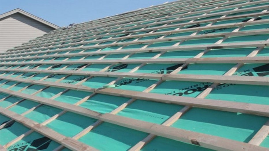
Above sheathing ventilation (ASV) is achieved by having continuous air flow between the roof sheathing and the metal panel system.
Nonetheless, if a layer of wood sheathing is placed directly on the insulation and then the metal roofing placed directly on top of that, the metal roofing will tend to get warmer in the sun than in a ventilated condition. Therefore, metal roofing manufacturers often recommend providing an air gap between the metal roofing and the sheathing. This is achieved with furring strips ran vertically to assure air flow, and then run horizontally to support the roof. The spacing and details of these supports should be determined by a structural engineer who can perform the needed analysis and calculations, taking into account the panel strength and imposed loads from snow, wind, etc.
Is this approach effective? A series of studies undertaken at Oak Ridge National Laboratory and sponsored by the Metal Construction Association has determined the answer is yes. These studies used a common asphalt-shingled roof without any ventilation above the sheathing as the control case. Then different versions of a metal roofing system with ventilation between the sheathing and the roofing were tested and compared to each other and the asphalt-shingled roof. The results found that “all test roofs were highly effective in reducing the heat flows through the roof and ceiling, and in reducing the diurnal attic temperature fluctuations.” (References below)
Clearly, paying attention to ventilating the roofing system, regardless of the type of construction, can make a difference in the overall performance of a roof. To find out more about ventilated roofing systems for a current or upcoming project, contact your local MBCI representative.
References:
Performance Evaluation of Advanced Retrofit Roof Technologies Using Field-Test Data – Phase Three Final Report
Metal roof and wall panels have many test standards they must meet under certain environmental conditions. Test standards that are specified for metal panels in our industry are ASTM E283 (air leakage) and ASTM E331 (water penetration) for wall panels, and ASTM E1680 (air leakage) and ASTM E1646 (water penetration) for roof panels. While the corresponding tests are similar, the orientation of the panels is a little different for the wall and roof panels. Here we’ll take a brief look at these testing protocols and what they mean for the integrity of the metal panel system at hand.
For air leakage tests, the protocol has been to test at a specified pressure. It should be noted that some manufacturers have changed it from the standard as many in the market are testing at a higher pressure. And while it’s true that you are going to have air pass through, you want the air to be minimized. Air leakage is tested in terms of cubic feet per minute, with a lower number indicating a better, more efficient product. For water penetration testing, water is sprayed and is tested for the water getting through the seam or side lap of the panel system.
The purpose of air leakage and water penetration testing is to establish air and water infiltration rates on the referenced test specimen in accordance with ASTM E283 and ASTM E331.
Metal Wall Testing Standards
As indicated above, the wall test standards are: ASTM E283 (Standard Test Method for Determining Rate of Air Leakage Through Exterior Windows, Curtain Walls, and Doors Under Specified Pressure Differences Across the Specimen) and ASTM E331 (Standard Test Method for Water Penetration of Exterior Windows, Skylights, Doors, and Curtain Walls by Uniform Static Air Pressure Difference).
The procedure for ASTM E283 is as follows: 1. Seal off test unit and measure air leakage (extraneous leakage); 2. Unseal test unit, then re-measure (total system); 3. Subtract extraneous air from total air = Performance.
According to ASTM, this test method is a “standard procedure for determining the air leakage characteristics under specified air pressure differences at ambient conditions.” Furthermore, the air pressure differences across a building envelope can have significant variation with numerous factors acting to affect air pressure differences relative to the particular building environment. For instance, the test method described is for tests with constant temperature and humidity across the specimen. These factors should be considered when specifying the test pressure differences to be used.
Additionally, rates of air leakage are sometimes used for comparison purposes but these comparisons would only be valid if the tested/compared components are of essentially the size, configuration, and design.
Using a Pass/Fail criteria, “Pass” results of this test indicated that water did not penetrate through control joints in the exterior wall envelope, joints at the perimeter of openings, or intersections of terminations.
The laboratory test procedure for ASTM E331 dictates that the test is conducted for a specified duration with water applied at 5.0 gal/ft 2 hr. at a specified pressure. The test has applied pressure and water spray for a period of 15 minutes.
According to ASTM, this test method is a “standard procedure for determining the resistance to water penetration under uniform static air pressure differences.” Furthermore, in applying the results of tests by this test method, ASTM points out that “the performance of a wall or its components, or both, may be a function of proper installation and adjustment. In service, the performance will also depend on the rigidity of supporting construction and on the resistance of components to deterioration by various causes, vibration, thermal expansion and contraction, etc.,” noting that exact simulation of real-world wetting conditions can be difficult (i.e., large wind-blown water drops, increasing water drop impact pressures with increasing wind velocity, and lateral or upward moving air and water) – and that it may depend to some degree on the design.
Metal Roof Test Standards
The Roof Test Standards are ASTM E1680 (Standard Test Method for Rate of Air Leakage Through Exterior Metal Roof Panel Systems) and ASTM E1646 (Standard Test Method for Water Penetration of Exterior Metal Roof Panel Systems by Uniform Static Air Pressure Difference).
According to ASTM, test method E1680 covers the determination of the resistance of exterior metal roof panel systems to air infiltration resulting from either positive or negative air pressure differences. The test method described is for tests with constant temperature and humidity across the specimen. (This test method is a specialized adaption of Test Method E283.)
ASTM literature explains that variables such as the slope of the roof and other factors can affect air pressure differences and, therefore, affect the implications of the resulting air leakage relative to the environment within buildings. Just as with wall panels discussed earlier, these factors need to be taken into consideration when specifying the test pressure difference to be used.
ASTM describes its E1646 test method as a “standard procedure for determining the resistance to water penetration under uniform positive static air pressure differences, and simulates win driven rain imposed on sidelaps and rain that is free to drain while building a water head as it flows.” For this test method, the slope of the roof is a significant factor.
According to ASTM, this test method covers the determination of the resistance of exterior metal roof panel systems to water penetration when water is applied to the outdoor face simultaneously with a static air pressure at the outdoor face higher than the pressure at the indoor face, that is, positive pressure. (This test method is a specialized adaption of Test Method E331.)
To learn more about MBCI wall and roof panels, please visit www.mbci.com.
Installing metal roofing and siding requires placing and aligning metal panels over the structural supports. But ultimately it requires installers to spend a fair bit of time fastening them in place, typically using a great many fasteners. It is easy to get complacent about this repetitive activity, but the reality is that every fastener plays a crucial role in the integrity and longevity of the installation. Properly selecting, installing, and using the right tools, allows for a proper fastening process that assures a weathertight installation. But if a few fasteners are installed poorly, causing water or air leaks, then the installer is called back to correct the condition. Do a lot wrong, and warranties can be void, with the durability of the building left compromised, possibly requiring a total do-over.
What’s the difference between a good fastening installation and a problematic one? Here are some of the things to pay attention to onsite:
Fastener Types:
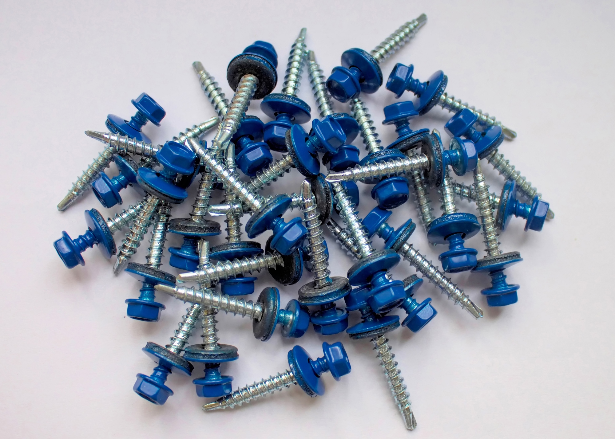
The most common type of fasteners used in metal buildings are self drillers, which vary based on diameter, length, head shape, and material. They are also specifically designed for use in metal substrates. Different fasteners are also available for wood versus metal, and either type can be sized for different substrate and panel thicknesses. Zinc alloy or stainless steel fasteners are common choices for durability, longevity, and avoiding galvanic action with other metal products. Selecting and using the right fastener type for each of the different locations on a metal building begins with determining what is being attached and what is it attaching to.
Fasteners can also be colored to match the roof or wall panel.
Weathertightness:
Fasteners of any type cannot be relied upon by themselves to keep out the elements. Instead, a sealing washer is used that is compressed between the fastener head and the metal panel as the fastener is tightened to form the weathertight seal. High-performance or long-life fasteners may be required for a durable approach to weathertightness and/or may be required by the metal building manufacturer to receive a weathertightness warranty.
Installation Process:
With the right fasteners onsite, the success of the installation now rests with the field crews. A few minutes to review the different fasteners and match them with the right tools and settings for installation is time very well spent. Since electric screw guns with or without impact drivers are common on the jobsite, it’s easy to think any tool will do, when it probably won’t. The wrong tool at the wrong setting can place too much torque or other force on the fastener, causing it to crush or damage washers or even the metal panels. Impact drivers are rarely needed in most cases and, while the fastening needs to be tight, overtightening is never a good thing.
Fastener Locations:
In addition to weathertightness, fasteners provide a structural function as well. Their location and spacing will directly correlate to the ability of a panel to resist wind and other forces after installation. Therefore, it’s always best to use information prepared by a professional engineer on the proper fastening locations, spacing, and sizes. The calculations behind such information can prove to be the difference between a successful installation and one that creates problems.
Understanding the importance of fasteners and the role they play in the integrity of the building, and corresponding warranties, allows installers to see beyond the repetitive task of fastening and into the craft of assembling a durable, long-lasting building. To find out more about fasteners for metal products and systems for your next project, contact your local MBCI representative.
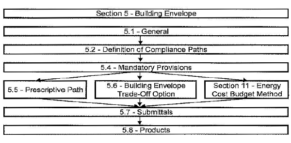
For a given assembly, if the right information is not specified in conjunction with the desired R-value, the designer will likely not achieve the results he or she expects. This can lead to code compliance issues as well as poor performance of the finished building. Therefore, a more thorough approach must be considered to ensure the specified assembly will be building energy efficiency code compliant. Where to begin? When looking at proper test methods to determine thermal resistance of metal panels, the place to start is ASHRAE 90.1 Chapter 5 (Building Envelope) and Appendix A.
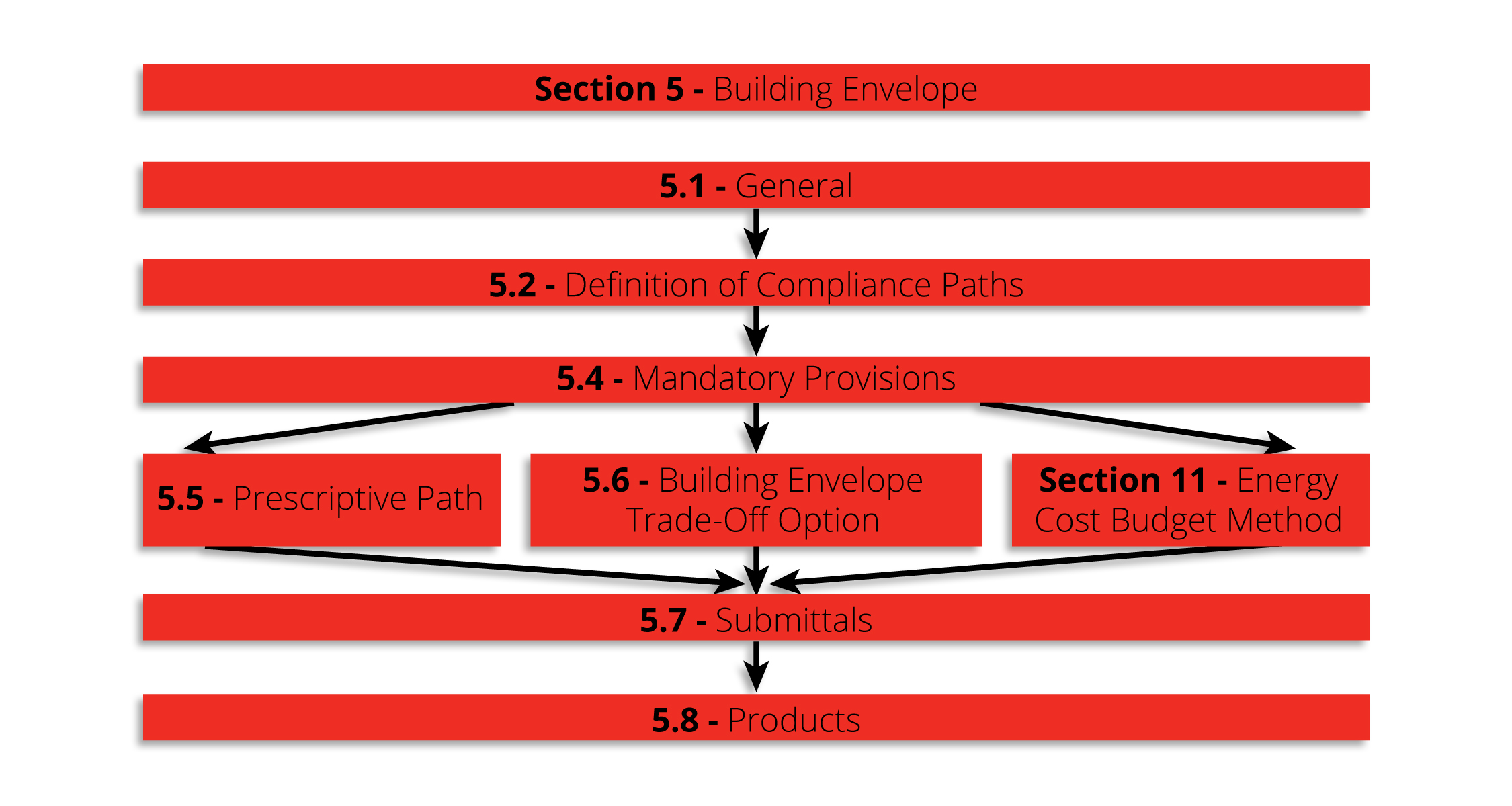
ASHRAE 90.1 Section 5 specifies requirements for the building envelope.
Code Compliance for Thermal Resistance
The most widely accepted energy efficiency standard for commercial construction in North America is ASHRAE Standard 90.1. This standard provides both a prescriptive and a performance path to be chosen at the designer’s option. The prescriptive path is most commonly used. It also provides the baseline performance level that is used to determine compliance for the performance path, so understanding this set of requirements is critical. Within the prescriptive path, two possible methods of compliance are available to determine the minimum thermal performance of opaque areas on the building envelope. Section 5.5.3 is the pertinent passage and it reads:
Minimum rated R-values of insulation for the thermal resistance of the added insulation in framing cavities and continuous insulation only. Specifications listed in Normative Appendix A for each class of construction shall be used to determine compliance.
Maximum U-factor, C-factor, or F-factor for the entire assembly. The values for typical construction assemblies listed in Normative Appendix A shall be used to determine compliance.
Exceptions: For assemblies significantly different than those in Appendix A, calculations shall be performed in accordance with the procedures required in Appendix A.
What does this mean? Basically, there are standard types of construction that ASHRAE recognizes and if you have a wall that fits the description in Appendix A, you don’t have to test or do anything special to determine its thermal resistance. Appendix A provides tables based on calculation methods that have been derived on the basis of previous tests and general experience. What is perhaps less obvious is that if your assembly is adequately described by one of the standard assemblies in the Appendix, you may NOT use a tested or modeled value in place of the values in the table, even if that value has better performance! (i.e., lower U-factor) This is explained in Section A1.2.
The reason the code is set up this way is to prevent people from building unrepresentative assemblies that achieve high performance in the lab but are likely not built to the same specifications in the actual building.
Conversely, if the assembly you want to use is NOT adequately described in Appendix A, the appendix goes on to specify which methods are acceptable to determine the U-factor based on the assembly to which it is most similar. This is covered in Section A9. Two and three-dimensional finite element models are always acceptable and in some cases, simplified calculation alternatives are also available. Note that hot box testing is not always allowed.
Conclusion
To summarize, whether using a prescriptive or a performance path, the first and last stop when determining thermal resistance for metal panels is ASHRAE Standard 90.1 Chapter 5 and Appendix A. Designers would be well advised to familiarize themselves with the Standard and the specific set of requirements for their particular scenario in order to utilize proper testing methods for high-performance results.