The Importance of Vapor Seals in IMP Installations

Insulated metal panels (IMPs) used for building envelopes offer great simplicity in terms of enclosing a building in an attractive, energy-conscious manner. However, they require somewhat different thinking in terms of design and installation compared to conventional single skin panels on metal building with separately installed fiberglass insulation and vapor liners. That’s because, while the insulation aspect of IMPs is well controlled in the factory, the air and vapor sealing aspects are entirely in the hands of the installers in the field.

Why is vapor sealing a concern? Because it can make or break a building envelope. Airborne moisture that travels through seams, joints, or gaps between IMPs or between the panels and the structural steel can condense and wreak havoc on the integrity of the wall system. If that condensed moisture makes its way to unprotected edges of metal, then rusting, staining, and deterioration can occur. If it collects and drains out the bottom of the panel, then a building owner may mistakenly think that the IMPs are leaking water. If the moisture works its way inside a panel and becomes trapped it could freeze in cold climates or applications, and push panels enough to make unsightly or fail to perform as intended.

How does an installer of insulated metal panels avoid these issues? By properly using sealants as recommended by the IMP manufacturer to close the gaps and assure a vapor-tight installation. Here are the key things that installers need to pay attention to:

Sealant Types

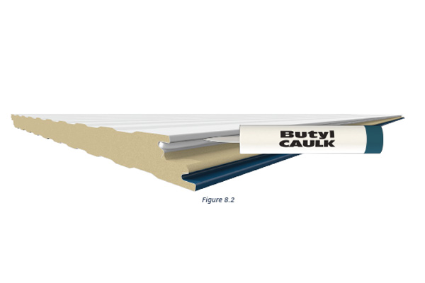
In most cases, butyl caulking is the recommended sealant for panel joints and perimeter attachments, although urethane sealant may be called for in some cases. For fire-rated panels, silicone sealants are usually required. The important caveat for all of these sealants is that they are most successfully installed when they’ve been stored within acceptable temperature ranges. In cold weather, they may need to be kept in a warming bin; in warm weather they must be kept out of direct sunlight.
IMP
Apply continuous non-curing butyl sealant to the interior panel joint with a bead size of approximately 1/4″ as shown above.

Tools to Use

Applying any of the needed sealants will require using the proper tools. Manual caulking guns don’t provide the consistent quality of application needed, so electric or pneumatically operated applicators are required.

Sealant Location

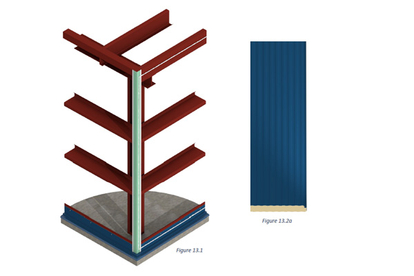
For typical building applications (non-freezer/coolers), the vapor sealant is placed in the interior panel joints when IMPs are installed vertically. For refrigerated spaces, the sealant is commonly placed on the exterior. If the IMPs are installed horizontally, then it usually is sealed on both the interior and the exterior panel joints to help with weather sealing as well. Note that the final placement of the sealant, as well as type and location, is actually the responsibility of the mechanical contractor/architect and not the panel supplier as it is to be based also on the mechanical design of the building envelope. In addition, the entire perimeter of the panels where they meet the building structure needs to be sealed. This includes the base flashing, interior corner trim, and eave struts. Further, marriage beads of butyl sealant must be placed at all panel terminations.
IMP
Panel Installation – Sealant

Sealant Continuity

In order to be effective, all sealant and caulking must be fully continuous. That means that the thickness of the sealant bead must be consistent and thick enough to fully close all gaps between or around IMPs. It should not be overdone, however, since too much sealant will ooze out between panels that are pressed together, causing a bit of a mess on one side of the other. Sealant continuity also means that it can not be interrupted due to poor adhesion. Therefore, before any sealant is installed, the application surfaces must be cleaned and dry to be sure that full adhesion is achieved. Always check with the panel suppliers details for minimum bead size and critical locations.

Factory-Installed Option for IMP

Some IMP manufacturers offer the option of having sealant pre-installed along the edges of the IMPs. Since the panels are wrapped and sealed for shipping, the sealant is protected and should be ready for use onsite. However, in this case, it is incumbent on the installers to handle the panels quite carefully, since the inadvertent placement of a hand over the sealant can damage it or deform it enough to render it ineffective. This factory-installed option offers a labor saving in the field but must be checked during installation and can be impacted by time climate depending on the time of year. Field application, while requiring more labor, does provide greater onsite flexibility for installers. Nonetheless, in all instances, the installer must ensure the sealants are properly located.

By paying attention to the details of sealing and caulking, a metal building constructed with IMPs will be a quality installation that will hold up quite well over time. To find out more about IMP metal products and systems that can help your next building be more vapor- and weathertight, contact your local MBCI representative.
Sustainability and Metal Buildings

The movement of the construction industry to create buildings that are more sustainable throughout their life cycle continues to be a fundamental part of a well-designed and well-constructed building. This comes from the building owners who are expecting it, designers who are more skilled at achieving it, construction companies who have incorporated it into their workflows, and manufacturers who have invested significantly in it. These sustainability efforts include the design, fabrication, and construction of pre-engineered metal buildings across the country.

A number of different certification programs (LEED, Green Globes, The Living Challenge, etc.) promote and can independently certify buildings as meeting different levels of “green” or “sustainable” designs. And the recently released International Green Construction Code has been adopted by a number of localities to codify green design and construction. While the details of these programs vary, they all address some fundamental aspects of buildings, and all apply to metal buildings.

Building Site Impacts:

Shop fabrication of metal buildings means the onsite work can be focused to stay close to the building footprint. Once built, the roofs of metal buildings can further reduce site impacts. For example, metal roofs provide an excellent opportunity to collect rainwater so it can be used for non-potable purposes, such as landscaping or toilet flushing. Further, by specifying metal roofing with a high Solar Reflectance Index (SRI) value, the roofing remains cooler than a dark-colored roof and reduces the so-called “heat island effect” surrounding the building.

Reduces Energy Usage:

Metal buildings can also be designed and constructed to create an energy-efficient building enclosure. The Metal Building Manufacturers Association (MBMA) publishes an Energy Design Guide for Metal Building Systems, available at www.mbmamanual.com, which can help in the process. As MBMA points out, builders can “select the best balance of high-performance roof and wall insulation (including fully insulated metal panels), windows and doors, and foundation insulation that works best and saves the most energy and money when considering all the project requirements.” A metal building with a sloped roof can also be the ideal base to support solar panels that can provide an onsite source of renewable energy for the building to capitalize on.

Responsible Material Usage:

The construction industry has become attuned to looking at the impacts of materials over their full life cycle, and this includes the metal building industry. The MBMA has taken the lead on preparing an industry-wide Life Cycle Assessment (LCA) (http://www.mbma.com/Life_Cycle.asp) that includes primary structural steel frames and secondary structural steel (purlins and girts), along with roof and wall products used in metal buildings. MBMA has also prepared Environmental Product Declarations (EPDs) based on the LCA and industry-wide product category rules. By using this information, designers, building owners, and constructors can determine the environmental impacts of metal buildings from the extraction of raw materials through manufacturing and preparation to ship to the construction site (“cradle to gate”). The fact that steel products of all types contain a significant percentage of recycled material, and can be again recycled at the end of the service life of the building, helps present a more sustainable picture of steel than does some other building products. Further, the shop fabrication of components helps eliminate construction waste on the job site.

Sustainability
At MBCI, we take LEED project documentation seriously and issue only project-specific documentation for USGBC submittals, so please contact your sales representative for LEED documentation on existing contracts.

Indoor Environmental Quality:

The interior spaces of buildings are generally considered sustainable when they protect the health and well-being of the people who use the building. In the regard, metal buildings provide some advantages over others. First, many of the metal building components can be pre-finished before ever arriving at the site. This means that onsite finishing, which can release harmful volatile organic compounds (VOCs) or other substances into the air, are notably reduced or eliminated a the building location. Further, the structural flexibility offered by steel construction means that windows, doors, and skylights can be appropriately spread throughout a building to provide natural daylight and exterior views, which have been shown to have great benefits to the people who work in, visit, or otherwise use the buildings.

Overall, it is the full interaction of all parts of a building, including the owners and users of a facility, that will determine the final sustainability of any building. Nonetheless, it is clear that metal buildings can be a great place to start on the sustainability path. To find out more about metal products and systems that can help your next building be more sustainable, contact your local MBCI representative.
Texas Department of Insurance Windstorm Inspection Program

Are you involved with a building project along the Gulf Coast of Texas in which metal roofing or siding is involved? If so, obtaining a building permit may be subject to compliance with the Texas Department of Insurance (TDI) Windstorm Inspection Program. Here is some information that can help.

What is the TDI Windstorm Inspection Program?

In 1987, the Texas Legislature enacted HB 2012 with a requirement to mitigate losses to structures due to hurricanes along the Texas Gulf Coast. On January 1, 1988, the Texas Department of Insurance (TDI) began administrating the Windstorm Inspection Program in support of this legislation. The program is centered in Austin, with four other field offices also located along the Gulf Coast.

Where does the TDI Windstorm Inspection Program apply?

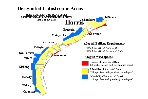
The Windstorm Inspection Program applies to all commercial and residential structures located primarily along the Gulf Coast of Texas. TDI has designated specific areas as catastrophe areas, also known as Texas’ First Tier Countries. The affected countries include Aransas, Brazoria, Calhoun, Cameron, Chambers, Galveston, Jefferson, Kenedy, Kleberg, Matagorda, Nueces, Refugio, San Patricio, Willacy and certain cities east of State Highway 146 in Harris County (La Porte, Morgan’s Point, Pasadena, Seabrook, Shoreacres).

Designated Catastrophe Areas

What is the Texas Windstorm Insurance Association?

The designated catastrophe areas often use Texas Windstorm Insurance Association (TWIA) as the insurer of last resort for the wind and hail portion of their building insurance. To qualify for wind and hail insurance through TWIA, all new structures plus any alterations, additions, or repairs to existing structures (including re-roofs or roof repairs) located in the designated catastrophe areas must be constructed and inspected according to the building specifications adopted by TDI.

How are Building Permits Affected?

All building work needs to meet the requirements of the adopted building codes in Texas (currently the 2006 version of the International Building Code and the International Residential Code). However, in addition to the codes, the TDI requirements must also be complied with in the designated countries. This is similar to other parts of the country that experience severe weather events (e.g., Dade County, Florida) where additional requirements above the code have been instituted for safety reasons. At the time of building permit application, evidence will need to be shown of TDI compliance in design documents; therefore, many times the local TDI office is contracted first and an application is submitted (Form WPI-1). Then, during construction, a TDI certified inspector (usually an engineer) will inspect the work, as will the regular building inspectors. Compliance will need to be shown with the TDI requirements (Form WPI-8) in order to obtain final sign off and a Certificate of Occupancy.

What Building Products are Approved for Use?

In order to be compliant with TDI standards, building products must be independently tested and shown to be able to withstand different levels of severe weather. For products like metal roofing and siding, the testing needs to include the method of attachment and the substrate type (metal, wood, etc.). Product evaluations are available by product type (such as “Exterior Coverings” for metal siding or “Roof Coverings” for metal roofing) and then by manufacturer all by either contacting a local TDI field office or on TDI’s website: www.texas.gov/wind/prod/index

For more information on this program visit http://www.tdi.texas.gov/wind/index.html or email Windstrom@tdi.texas.gov. To find out more about metal roofing and siding products that meet the severe weather requirements, contact your local MBCI representative.
 

Proper Cutting and Cleaning of Metal Building Panels

Metal building panels, whether for roofing or walls, are manufactured with a long-lasting and durable finish of different types and in many colors, allowing the panels to hold up and look great for decades. However, once they get to the building they may need to be cut to fit a field condition, or they may need to be cleaned either during or after installation for any number of reasons. Innocently doing either, without understanding that doing it the wrong way could compromise the integrity of the finish, can be disconcerting at best or warranty-buster at worst. Here are a few tips for the proper cutting and cleaning of metal panels.

Cutting Metal Panels:

Field cutting of panels is certainly allowed and acceptable to manufacturers and is common, particularly at framed openings. However, there are two things to pay attention to here:

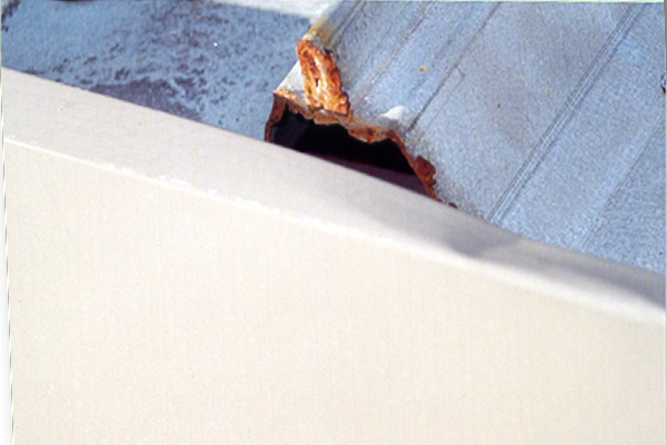
  • Cutting Method: If field cutting is required, the panels must be cut with nibblers, snips or shears to prevent edge rusting. Do not cut the metal panels with saws, abrasive blades, grinders or torches. Abrasive saw blades, grinders and torches can leave irregular or rough edges that are no longer coated or finished, thus causing rust and corrosion.
Metal
Corrosion on this panel edge is due to an abrasive saw blade cut.
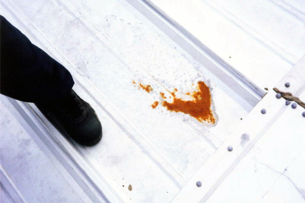
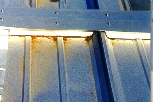
  • Cutting Location: All cutting of metal will produce fine particles, or swarf, that will fall from the cut. If this swarf falls on the roof, it can cause permanent staining and, if enough of it accumulates in one place, it could rust completely through the metal roof panel. Therefore, never cut metal panels on the roof or over other metal panels. It is best to cut the panel down on the ground where the swarf can be captured and disposed of.
Metal
Accumulated swarf from cutting is staining this metal panel.

Cleaning Metal Panels:

Metal panel manufacturers will usually provide information and directions for cleaning. A typical set of cleaning recommendation follows, based on a progression of cleaning levels—start with number 1 and work your way down the list for tougher jobs.

  1. For simple cleaning, water and mild detergent will often be all that is needed. However, bleach should never be used, since it can change the finish color or interact disastrously with certain metals.
  2. For water-soluble dirt or other deposits requiring more complete cleaning, a solution of hot or cold water mixed with detergent is appropriate. In a container of water, use a 5 percent solution of commonly used commercial (non-industrial, non-bleach) mild detergent, so as not to have any deleterious effect on the painted metal surface. Use a cloth or a soft-bristle brush for application of the cleaning solution, followed by an adequate rinse with clean water. Alternatively, pressure-washing with a 40° tip is also an option.
  3. For non-water-soluble deposits such as tar, grease, oil and adhesives, a solvent or alcohol-based cleaner may be required. In this case, since most organic solvents are flammable and/or toxic, they must be handled accordingly. Generally, keep them away from open flames, sparks and electrical motors. Use adequate ventilation, protective clothing and goggles, and read the manufacturer’s Material Safety Data Sheet (MSDS) of any solvent used for any other specific safety details. The following are among the cleaners recognized by manufacturers for this type of non-water-soluble cleaning:
    1. Alcohols
      1. Denatured alcohol (ethanol)
      2. Isopropyl (rubbing alcohol)
    2. Solvents
      1. VM&P naptha
      2. Mineral Spirits
      3. Kerosene
      4. Turpentine (wood or gum spirits)

Regardless of the level of cleaning required, never use wire brushes, abrasives, or similar tools that will abrade the surface coating and leave scratches or other finish damage and lead to corrosion. Further, keep in mind that any misuse or abuse of any of the acceptable cleaning agents will automatically void any manufacturer’s warranty for the affected surfaces.

By using the tips above to properly cut and clean metal panels, installers can avoid the problems of corrosion, staining or other surface damage. Thus, the integrity and beauty of the finish is maintained without any impact on the warranty. To learn more about metal panel finishes, cutting, cleaning and warranties, contact your MBCI representative.

How Energy Codes Influence Metal Roof Panel Selection

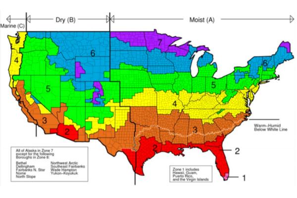
On a very basic level, specifiers can look at a climate zone map and get an idea of the metal roof panel best suited to a specific geographic region. The issue, however, is actually much more complex. One must know that overlooking any detail could result, not only in less-than-ideal performance, but also in costly project fail, often related to the project not meeting required energy codes or other standards. With this in mind, an important initial question to consider is how to select metal roof panels that conform to new and fast-changing energy codes and their designated climate zones.

To begin making wise considerations, the architect must know what codes are in play. For instance, is it IECC or ASHRAE 90.1? Which year of the code/standard? Are there additional local code requirements? Even if a state adopts a particular energy code, it doesn’t necessarily mean that all jurisdictions will adopt the code at the same time. Along with this, some local jurisdictions may have their own or additional requirements. To be successful, it is imperative to know what the regional project goals and requirements are. This will require research prior to specifying the metal roof panel and its assembly.

Using IECC and ASHRAE 90.1 for Energy Code Compliance

Three of the basic metal building roof panel types are single-skin standing seam, screw-down and insulated metal panels (IMPs). When using the tables in IECC and ASHRAE 90.1 for metal building roofs it must be remembered that these tables are based on single-skin standing seam roof panels and purlins that are 5′ on center. The tables provide the required R-values and/or U-factors based on climate zones, along with other assembly requirements noted with each tables. In the Appendix of some versions of ASHRAE 90.1, there are allowances for modified roof assemblies, including screw-down metal roofs.

Energy Code
DOE-Developed Climate Zone Map

Often, in certain climate zones, the required R-values and U-factors may be so stringent that the logical first consideration is to use insulated metal panels. IMPs are a great choice for offering high insulation properties in a top-of-the-line product and the R-values and U-factors are readily available for use in compliance calculations.

Keep in mind when deviating from the prescribed assemblies in IECC and ASHRAE 90.1, calculations will be required to show compliance, along with modeling and/or the use of approved compliance software, such as COMcheck.

Making Informed Decisions

Selecting the right metal roof panel is an important step to achieving energy code compliance. Even though energy codes can be complex and are constantly evolving, by making informed metal roof panel selections you will add to the overall success of your project.


Top Five Tips:

  • Know your code. Find out what energy code is required for your project.
  • Know your zone. Requirements vary by climate zone. Identify your project’s climate zone.
  • Understand your options. Deviating from specified assemblies will require approved proof of compliance.
  • Choose wisely. Research the properties and assembly requirements of any metal roof panel. Use this information in conjunction with energy code requirements to make wise choices.
  • Call with questions. Call the manufacturer with questions before you get too far down the road.

Understanding R-Values and K-Factors in Considering Thermal Resistance

Described in their most basic terms, R-value is a measure of heat resistance, while U-factor (also know as U-value) is a measure of heat transfer (heat gain or loss). The lesser known K-factor is simply the reciprocal of the R-value of the insulation divided by the thickness. What they all have in common is a relationship to the effectiveness of insulation material in resisting heat flow through a roof or wall element. There are different ways that this would be spec’d from a manufacturer to an architect or engineer. While the terminology might be familiar, the specifics are not always as clear cut as they seem. Understanding the differences will allow architects to make smart and effective choices to suit a given project’s needs.

Let’s consider some of the variables that might have an impact on what to look for and which metric to spec. As means of illustration, put yourself in the shows of a fiberglass or insulation supplier. You have a product, you know what it’s rated to, you know what the performance capability is, it’s been spec’d out to you—and you submit the bid based on those factors. But at that point you inevitably lose control over how the specs would actually get implemented. For instance, the architect may take that spec and incorporate it into a wall where it’s not used the most efficient way. This may not even be the result of a mistake; it could just be that other project elements have taken over.

Factor
Choosing the right insulation for the project can provide the building significant energy savings.

A good example would be stud walls. The fiberglass insulation supplier might indicate a given R-value, such as R-19. This would be the heat resistance value. The architect might spec and submit that bid to supply x number of square feet of that insulation based on that R-value. However, it could be cut or delivered in rolls and designed to fit between the metal studs. Metal studs are much more conductive than insulation and they provide an alternate path for the heat to flow through the assembly, almost irrespective of what the R-value and insulation is. Given these factors, the architect might have to make tradeoffs.

Choosing U-Factor

Because of all the variables encountered with R-value, U-factor is actually more recommended and reliable, and it more appropriately meets code requirements.* The concept of U-factor relates to the heat transfer coefficient but is described in the code as total heat flow per unit area through the assembly inclusive of all the short circuits as it is planned out to be built. So, an architect or engineer would know the stud spacing, the cladding material, the interior finish material and the R-value of the insulation. With that information in hand, one can go to a textbook, ASHRAE 90.1 or the ASHRAE Book of Fundamentals and find the U-factor for the assembly. It is this U-factor that is actually compared against the code requirements. It’s a better way to spec because it already takes into consideration all those things that come into play and encourages the use of suppliers (such as MBCI) that staff people who can help do those calculations or give assistance as opposed to saying, “I need R-19” and then wind up with a building that’s bridged or has more short circuits than anticipated—and having the building not perform as needed. This, in essence, is the key difference between R-value and U-factor.

A Word About K-Factor

As for K-factor, as noted this is the thickness of the insulation divided by the R-value. Its intention is to spec out an insulation when you’re not entirely sure what thickness it will be at the time you spec it out. This is fine for design-build scenarios but not a good practice for a hard bid. Bottom line: U-factor is most often the most reliable choice.

*Note: The code defines U-factor as discussed but underlying heat transfer theory may describe U-factor as 1/R-value. Insualtion suppliers might invert it and make it an R-value (but doesn’t take all the variables into consideration). Therefore, an architect would be advised to specify a “U-factor in compliance with ASHRAE, ” which includes thermal bridges, joints, etc.

The Case for Day One Weathertightness Warranties

Once upon a time, a “standard warranty” was indeed the industry standard for weather tightness warranties in the metal roofing realm. To make a long story short, this meant that manufacturers supplied a “manufacturer’s standard warranty” based on an initial review of the details to ensure that the roof could be properly installed but left it up to others to ensure that the details were followed. If the roof was not properly installed and resulted in a leak then the manufacturer’s warranty did not cover it. At this point, the project had been closed out and the installer was long gone, sometimes even out of business. The owner, architect, general contractor, installer and manufacturer were then at odds with each other leading to dissatisfaction and frustration all around.

Warranty Evolution

In the mid ’90s, the Single Source or Day One warranty was born and quickly caught on throughout the metal roofing industry. Generally, this warranty required that the roofing contractor come to the manufacturer’s training course to be trained in the proper installation of their roof system(s). In addition, the manufacturer typically required inspections at the beginning, middle of the roof installation with a final inspection just before the crew demobilized from the project. Once the warranty was issued, the manufacturer was responsible to the building owner from the date of substantial completion for the weathertightness of the roof. To be sure, there are still terms and conditions to the warranty, just like with any type of product warranty. For instance, the warranties don’t cover leaks caused by natural disasters or damage caused by other trades on the roof. These warranties provide very good coverage and the best part is that the inspections greatly reduce the chance of a leak in the first place, which is what any building owner would want.

Warranties
Chain of Lakes Elementary School featuring Hunter Green SuperLok® Metal Panels

There is an overwhelming agreement on all sides that the evolution toward the Day One warranty has been a good thing for the industry. It has forced installers to do things right from the outset and has compelled manufacturers to come up with good, clear details for some of the more complex architectural elements that architects want to use such as dormers, hips, etc.

Conclusion

Manufacturers all want their roof installations to go smoothly, to look good, be trouble-free and perform as expected for many years. To that end, they are willing to work with specifiers, roofing contractors and others to provide assistance, training and job specific help as needed. To ensure that the roofs are properly installed, the specifiers and contractors need to work together with the manufacturers to ensure good communication about the requirements for the specific project and what each party needs to make the project successful.

What to Know About Dissimilar Metals in Metal Roofing Installations

While metal roofing is often used because of its resiliency, strength and longevity, there are circumstances under which corrosion and other reactions can become real issues, to the great detriment of the system’s performance and life cycle.  Some basic knowledge and awareness of common causes of galvanic corrosion (also called “electrolytic corrosion”) from the use of certain dissimilar metals, can go a long way in mitigating potential problems.

Lead and Copper with Metal Roofing

Metal
Lead from pipe penetrations can deteriorate the metal.

Lead and Copper are the biggest culprits when it comes to shortening the service life of metal roofing due to corrosion.  It almost goes without saying to make sure these metals don’t come into contact with the roof, specifically roofs with Galvalume Plus products.  Here we’ll take a brief look at some of the common problems that can arise.

Due to the high probability of corrosion, it is not advisable to use lead roofing products, such as lead roof jacks for pipe penetrations.

Additionally, graphite, which is the primary material in the common pencil, is extremely corrosive to aluminum and aluminum alloys.  Therefore, it is not advisable to write on a metal panel with a graphite pencil.  In time, the element will eat through the coating and it will rust out.  Eventually, you’ll actually be able to see whatever you wrote on there (that’s not what you want!).  Instead, using a Sharpie or a grease pencil will solve the problem with little to no effort.

Metal Roofing
Chemical damage caused by corrosion and other reactions.

Copper is another metal that does not react well with galvanized metal panels used in many metal roofing systems.  Contact between copper parts and metal roofing can greatly increase the likelihood of corrosion.  Some specifics to keep in mind:

Don’t use treated lumber, which has copper in it.  Sometimes, an installer will set some type of treated lumber post and place something on top of it.

Metal
Copper in condensation can eat through metal, damaging the structure.

Over the course of a year or even a few months, the panel will face deterioration at that spot since once moisture invades it will corrode the panel due to chemical reaction.  A possible solution to avoid this scenario if treated lumber or a lightning system with a cable is needed is to ensure the cable has aluminum instead of copper.

Another situation where copper can be an issue is with an AC unit on the roof.  The AC unit may have copper in the coils, and when condensation drips out on to the roof with copper in the water, those drips onto the metal roof will cause corrosion.  The solution in this case would be to install PVC piping all the way up the roof so the copper does not make contact.

Conclusion

An understanding of these and other potential corrosion pitfalls that exist from using dissimilar metals and knowing the basics behind galvanic reactions will provide a solid basis for the smart, proper selection of roofing installation metals.  With this knowledge in hand, problems can be eliminated before they occur, which in turn can save time, money, and resources, not to mention meeting the all-important goal of extending the life of the metal roof.

Respect the Module: Metal Roofing Panels are Modular for Good Reason

When installing metal roof panels, the sign of a successful installation can be seen in the way the spacing and alignment of the panels are held across the entire roof. Improperly done, the appearance suffers from standing seam lines that are wavy or non-parallel to roof edges. Even worse, the panels can be unduly stressed, causing the potential for failure of water protection. Installed properly, by being diligent about spacing and holding the modular layout to be square to the building, the results are clean, straight lines that allow proper performance of the roofing system.

Here are some basic tips for installing metal roofing panels that help ensure that the module is used as an advantage for first-class work.

Check the Building

Before starting the roofing installation, examine the steel structure and anything else that the roofing panels attach to or are impacted by. Is the steel out of square? Are the purlins properly aligned or are they bowed? Is the plane of the substructure within the tolerance of the manufacturer’s requirements? Discovering any irregular conditions in the building will require some adjustment to determine how to assure that the roofing can be installed properly and then remedy prior to starting.

Establish a Reference Line

The best way to ensure that the panels stay aligned as they are installed is to establish a fixed reference line along the rake edge of the building that is square to the building eave. Then, all measurements for spacing should be made from this reference edge line. A string line can be installed from the eave to ridge running parallel to the rake. The string line should stay ahead of the work and measure from the string back to each panel run. The string line is moved ahead as the roof installation progresses.

Improper module alignment
Improperly installed roof panels that do not maintain proper module alignment not only look bad but will result in a roof system not being able to function as intended for expansion and contraction as well as weathertightness.

Checking Panel Alignment

The alignment of the roof panels can be checked every run, but at a minimum, it must be checked every three or four runs. Measure from the rake support to the seam of the last completed panel run at the eave, endlap and ridge.

Holding Panel Modularity

Here are a few basic techniques as the work progresses:

  • For better clip alignment, the installer can pre-drill purlins at endlaps and ridge locations. The hole should be located at the leading edge of the clip so that an awl or punch can be inserted into the hole to align the clip and adjust accordingly.
  • In order to be sure the panel shape is held, use wood or other substrate to create blocking that can be inserted between the panel ribs and used in conjunction with checking the module and alignment of the panels as they are installed.
  • Keep as much weight as possible off of the panel while installing clips. Not only is it unsafe, but it can shrink width of the panel.
  • Use the correct combination of clips, insulation thickness and thermal spacers to maintain a level panel installation and prevent gaining or losing module size. See the manufacturers recommendations for each of these components based on the roof insulation system being utilized.
  • Use alignment straps purchased from the roofing manufacturer and install them on top of the purlins before insulation. These are factory stamped to receive the roof system clips based on their panel module.
Properly installed system
A properly installed system is apparent in the consistent alignment of the roof panels with the building and will perform as designed more many years of weathertightness.

Adjusting Panel Width

In order to maintain the modularity of a well-installed roof, the width of the panels may need some slight adjustments. Some roof systems can be adjusted by bending the sides of the backup plates slightly to make the panel connection at then endlaps and ridges either wider or narrower, but no more than ¼” per side. Other roof systems may be adjusted with the panel clips themselves. To stretch the panel width, install the clip at the endlap or ridge with the base angled away from the panel. To shrink panel coverage, install the clip at the endlap or ridge with the base angled toward the panel.

By following some of these simple techniques and paying attention to the reference lines for the roof, any deviations and corrections can be identified right away rather than discovering the problem later and requiring rework. Overall, these tips should result in a roof that is better-looking, faster to install, and more weathertight.

Reducing Peak Demand Costs with Cool Metal Roofs

Among the many benefits offered by cool roofs—including a decrease in urban heat island effect or increased roof system longevity—perhaps the most significant is a reduction in peak demand energy usage which directly affects building expenses.

Peak demand is the highest point in the day at which a building draws electrical consumption. A facility’s monthly utility rates are largely determined by the power usage level at this time, so anything that can be done to drive usage down will significantly reduce utility costs. As evidenced by their test values, cool roofs are an effective way to decrease air conditioning loads during peak demand times.

Cool roof values are expressed in terms of solar reflectance and thermal emissivity. The combination of these values is used to determine how hot a surface will become by its ability to reflect solar energy and radiate heat away from itself. Cool roofsare capable of reflecting solar heat away from a building by more than 70 percent. In fact, the U.S. Environmental Protection Agency estimates that ENERGY STAR® qualified roofing products can lower roof surface temperatures by up to 50°F.

According to Jeff Steuben, executive director, and Carolyn Richter, communications manager, Cool Roof Rating Council (CRRC), in a recent Florida Roofing article, “Building occupants can experience improved comfort as compared to a conventional dark roof, as the building’s interior is subject to less thermal flux and stays cooler during warm seasons,” and, “Reduced indoor temperatures lead to energy savings from reduced cooling energy loads.”

Along these lines, contractors can also access a CRRC-provided listing of cool roof rebates, codes and voluntary cool roof programs at: www.coolroofs.org/resources/rebates-and-codes.

Cool Roofing Longevity

In addition to energy efficiency, cool metal roofs are known for extended durability and longevity, with most products offering a 40-year finish warranty.

In fact, a well-noted extensive study, Natural Exposure Testing in California, conducted by the Oak Ridge National Laboratory, found that pre-painted metal roofing maintained higher levels of reflectance, over a three-year period, due to its ability to shed particulate matter, as compared to conventional roofing materials. Further, pre-painted metal roofing has been found to retain 95 percent of its initial solar reflectance over this same three-year period.
Increasing performance and energy savings, solar reflective pigments in cool metal roofs offer higher total solar reflectance and thermal emittance, even in darker colors. With cool roof technology, the ability for the roof to store heat and radiate that heat into the building after sundown is dramatically reduced.

Cool Roofs
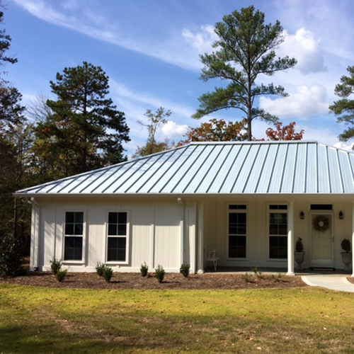
Heitmann Residence featuring a Cool Metal Roof

Cool metal roofs are proven to deliver environmental and performance benefits, of which the most significant to building owners is their contribution to the bottom line. Although savings will vary based upon geography, materials and insulation, the U.S. Environmental Protection Agency estimates that reflective roofs can save up to 40 percent of a building’s cooling energy costs.

When utilizing the U.S. Department of Energy’s Cool Roof Peak Calculator, contractors will discover that the total value of energy savings offered by a cool roof averages more than $1,000 annually in most climate zones for a typical commercial building. Furthermore, this applies to both cool roofing installed over both existing roof insulation and new insulation.

Proven Strategy

As established by documented study and significant heat build-up reduction levels, cool roofs are a proven strategy for supporting longer lasting roofs, reducing both utility costs and decreasing a building’s environmental footprint as Steuben and Richter conclude, “cool roofs are one of the most effective ways to obtain energy savings and environmental rewards through building envelope design and re-roofing projects.”

Find a sales representative