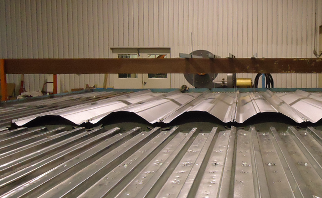
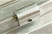
Among the most important factors to account for when specifying a standing seam metal roof are wind control and wind uplift. It is imperative to take the necessary measures to ensure the safety and efficacy of the metal roof. The wind clamp—an extruded piece of aluminum that is placed on the panel seams at clip locations—is one accessory that can be used to improve wind uplift characteristics on metal roofs, delivering substantial time and cost savings as these devices help mitigate risk of wind uplift and improve overall wind design.
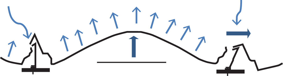
Standing Seam Panel Deflection as a Result of Wind Uplift
Why Use a Wind Clamp
A typical failure mode of a standing seam metal roof panel is the clip top pulling out of the panel seam when the panels are subjected to high winds. With a standard install of a standing seam panel, the seams just fold into each other. With enough pressure, wind will force seams to come apart—be it a vertical failure, horizontal movement of the seam or from clip disengagement. The clip top can then pull out of the panel seam.
The wind clamp resists the panel seam being opened, allowing for higher uplift loads. The purpose of wind clamps, in fact, is to prevent failures at the seam openings due to any deflection of the panel. The wind clamps provide more strength, thereby dramatically improving wind uplift performance.
The clamp is installed over the panel seam at clip locations, in the edge and corner zones of the roof. This allows the roof to resist the higher wind pressures in these zones, usually eliminating the need for additional purlins or joists. On large roofs, the savings can be substantial.
Another benefit is shorter installation time. Since additional purlins or joists are typically not required at the edge or corner zones of the roof, the building can be erected faster.
Choosing Wind Clamps
When choosing the type of wind clamp, it is important to consider the type of panel and the special features of the clamps. MBCI, for example, uses S-5!’s patented wind clamps, which work for two panel types—Ultra-Dek® and Double-Lok®. The S-5! wind clamps do not penetrate the steel, thereby eliminating the risks of corrosion and water leakage that can be introduced by a hole in the steel. Since the screws are hidden from the weather elements, it helps to maintain waterproofing.
Quantitative Difference with Wind Clamps
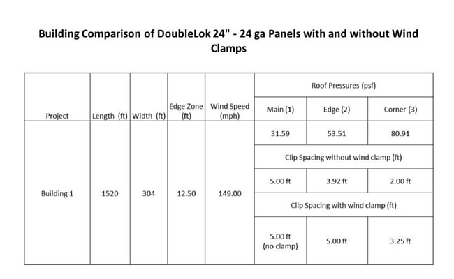
One of the biggest benefits of using wind clamps in the edge and corner zones is that usage minimizes the quantity of purlins needed, resulting in substantial cost savings. For example, let’s look at a comparison using MBCI’s Double-Lok 24” – 24 ga. panels with and without wind clamps.
In this example:
The use of wind clamps in the edge and corner zones eliminated 3,800 linear feet of purlins.
Assuming 8” x 2-1/2” Zee 14 ga. purlins were used, there would be a cost savings of $10,400.
Conclusion
Utilizing wind clamps to protect the investment of a standing seam metal roof can increase strength, make installation faster and lower overall cost.
When the conversation turns to sustainability, there’s a lesser known benefit to metal roofing that helps with the environment – and the building owner’s operations costs.
There are a number of reasons why metal roofs are sustainable. The most obvious reasons are that they’re long-lasting and durable, recyclable, and they’re a natural pairing with roof-mounted photovoltaic (PV) systems for alternative energy. A metal roof is like the Swiss Army knife of sustainable architectural products because of its versatile environmental benefits.
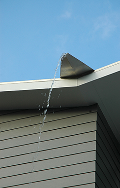
Conserve Water with Metal Roofing
Yet, one of the more important environmental benefits that sometimes gets overshadowed by these other qualities is a metal roof’s capacity for water conservation.
Many cities in the U.S. encourage water conservation in one form or another. Such practices come in handy during extended water scarcity, like the one California has experienced for the past few years (if not longer, depending on one’s definition of “scarcity”).
Reduce Flooding with Metal Roofing
Other places have the opposite problem. Flooding has most recently occurred in the Houston area, but is also a continuous problem in places like New York City, New Jersey and others. These flooding problems stem from unusually large amounts of rainfall, obviously, but also from the built environment’s inability to cope with rainfall because of the impermeable nature of surfaces in cities.
A metal roof can help when coupled with a storage device that captures the water and delays when it’s sent from the site into the city’s stormwater system. That captured water can be reused onsite for non-potable purposes, such as landscaping and toilet flushing.
Benefits to Reusing Rainwater
The benefits to capturing and delaying the release of rainwater don’t just end with helping a city to better manage rainfall for drought or flooding conditions—stormwater retention also helps a building owner’s checkbook.
Reusing rainwater means paying less for water that the local water utility has had to treat and send into the building. Owners can save some cash on their water bills while simultaneously easing some stress on the utility. It’s win-win.
If you’re familiar with the phrase “they get you coming and going,” well, municipalities are similar with water supplies. Sure, they charge for providing a facility with water, but many also charge to remove water in what’s called a stormwater fee. If that fee is calculated by the amount of water leaving the site (quantity), then reducing the amount exiting via the municipal system will again save the owner money.
Helping Clients and the Planet
Metal roofs with water collection systems aren’t going to miraculously solve all flooding and drought concerns, but every little bit helps. Sustainability strives to meet the triple bottom line of people, planet, and profit—and metal roofs have the capacity to meet all facets of the triple bottom line for more than what typically gets talked about. So, once you know the client’s goals and concerns on your next project, be sure to have a conversation of your own to find out how a metal roof can help achieve the client’s vision.
When it comes to specifying standing seam roofs, one type doesn’t fit all. While a standing seam metal roof system can be one of the most durable and weather-tight roof systems available in the industry, its benefits can be negated if you fail to understand the details in application parameters of the specific system. Do your research, though, and for your next design that requires an aesthetically pleasing and structurally sound metal roofing system, you can choose with confidence the standing seam metal roof system that suits your project to a tee.
How to identify a good standing seam roof system
A good standing seam roof system is one that can satisfy both the project’s specific design criteria and adhere to building code standards. Standing seam profiles can include those that are utilitarian or architectural in nature, are of numerous widths and profiles and have varying seam joinery (e.g., snap or field seamed).
Why specify a standing seam metal roof system
When properly installed, standing seam metal roof systems are an extremely effective and long-lasting material choice. Key advantages include:
Weather-tight roofing system
Can be engineered to withstand high winds (150 mph and higher)
Class A Fire-resistance rating from UL
Class 4 Impact-resistance rating from UL
Long service life—up to 60 years
Lightweight
Special clips designed to accommodate thermal roof expansion and contraction and various thicknesses of fiberglass insulation
Matching the roof system to the project
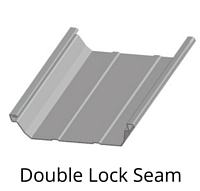
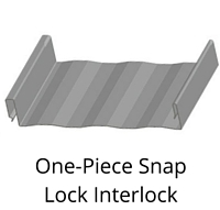
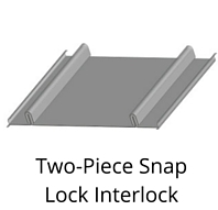
In basic terms, there are four unique styles of metal standing seam panels: Double lock seam, symmetrical seam, one-piece snap-lock interlock and two-piece snap-lock interlock. These styles can be further delineated by seam shape or profile, i.e. trapezoidal rib, vertical rib, square rib and tee rib. The choice of the rib profile, as well as the rib spacing is generally an aesthetic preference of the designer. Knowing which style will best suit a given situation will help ensure a successful installation.
Shown: MBCI Double-Lok®
Shown: MBCI LokSeam®
Shown: MBCI Craftsman™
Some criteria to consider are roof slope, roof run (distance from eave to ridge), weather conditions (such as ice or snow) and architectural features, i.e. hips, valleys, dormers, parapet walls, etc.
For instance, if your project has a roof slope of 1/2:12 you will need to ensure the product being installed is approved for this low pitch. In this case, you would likely use a “double lock” or mechanically “field-seamed” panel. You also want to ensure that all details are able to provide for a weather-tight seal even if temporarily submerged during a heavy rain. Field-seamed panels are also the best choice in areas that experience heavy ice and snow.
Additionally, it is imperative to recognize complicated design details that should be carefully specified and reviewed regardless of the roof slope. Design conditions that require special attention include: roof transitions, dead valleys, dormers, eave offsets, ridge offsets and offsets in parapet walls.
It cannot be overstated that you should always consult a metal roofing manufacturer about the capabilities of the standing seam metal roof system, including what warranties are available, prior to specifying it.
In the age of increased energy efficiency requirements in buildings, designers often find themselves spending time and resources squeezing performance out of systems with relatively little gain in efficiency. More and more, building insulation systems seem to fall into this category. The authors of the building codes recognize this as well and have reacted by turning their focus on other metrics like air infiltration where more substantial gains are to be had. A similar situation exists with lighting efficiency. However, when it comes to daylighting, designers are often pushed out of their comfort zone because lighting concepts and terminology is quite esoteric and difficult to comprehend.
m
The truth is that most people take light for granted and aren’t aware of the complexity of lighting for human activity and comfort. Probably the biggest reason for this complexity is the fact that the human eye is the only way we can judge light and although the eye is an evolutionary masterpiece, it has its own idiosyncrasies and no two eyes work identically. For instance, the typical human eye can discern shades of green at much greater accuracy than other colors and because of this sensitivity, green light is often perceived as brighter than other colors at the same energy level. Therefore, quantifying light level for human comfort and function must take this sensitivity into account, leading to some complexity. Here are some basic principles that you need to understand:
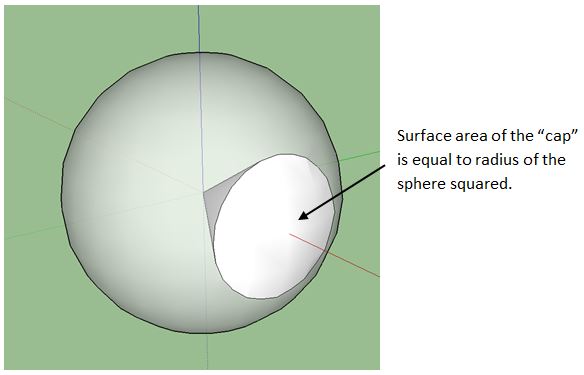
A steradian is a unit of solid angle measure. You can think of a 1 steradian solid angle as a cone cut out of a sphere with the apex of the cone at the center of the sphere and cross-section angle of approximately 66 degrees. A unique property of a 1 steradian solid angle is that the area of the semispherical “cap” captured by the cone is equal to the radius of the sphere squared. This makes it a convenient shape to use in measuring the amount of light projecting from a source at the apex of the cone through its interior and onto the cap because the amount of energy passing through any cross-section along the way is always the same. There are 4π, or approximately 12, steradian in a sphere.
Light is generated at the molecular level by the outer bands of electrons surrounding a given atom. When these electrons become excited at a high enough level, they emit a burst of energy in the form of electromagnetic radiation of a wavelength interval unique to the emitting atom in order to return to a lower energy state. If the energy level is just right, this wavelength will be in the visible light spectrum and viewed as a specific color. White light is formed when many atoms respond at various energy levels distributed across the entire visible spectrum in a pattern such that the energy transmitted is roughly constant with wavelength. The human eye is not responsive enough to discern the different colors hitting it, so an overall stimulation results in a static or “white” response. (There is a similar concept for sound as well, called “white noise”, when the ear cannot detect the individual vibration frequencies.)
The absolute brightness of light is given by the total energy it transfers through electromagnetic modulation. It is determined by summing up the energies transferred by each incorporated wavelength. As light travels from a point source, this energy spreads, causing the amount of energy arriving at a single point in space to decrease as that point is placed farther away from the light source. Brightness decreases with the square of the distance from which it is viewed. In other words, a light will appear ¼ as bright when viewed from a distance twice as far.
Because the human eye is more sensitive to green light than other colors, the brightness it perceives from different lights can only be effectively compared at the same color or wavelength. For light used for human function and comfort, it has been standardized to quantify the brightness at the 555 nanometer wavelength, which is near the center of green in the visible light spectrum, and then adjust for the effect of other colors consistent with how the human eye perceives them. Color is accounted for by weighting the energies transmitted at other wavelengths using the luminosity function. The resulting quantity is called perceived brightness. The luminosity function is similar to a bell curve and it represents how relative brightness of various colors is perceived by the typical human eye. As you might expect, the luminosity curve peaks at a wavelength near 555 nanometers.
Absolute brightness is measured in watts and should only be used when comparing lights of the same color. This should not be confused with power consumption, which is also measured in watts. Perceived brightness is instead expressed in candela and is the only way light of mixed color (on non-monochromatic) can be compared. A one candela light source with a wavelength of 555 nanometers transmits 1/683 of a watt of energy.
It is also important to be able to quantify total light output of a light source. Real-world light sources are not usually of equal brightness in all directions, so candela is not the best measurement to use. To account for spatial variation, total light output is defined as the sum total of light passing through every point in a cross-section of a one steradian solid angle, considering a light source at the apex, divided by the area of the section. This results in the same quantity regardless of the location of the cross-section. So, if a light were to transmit one candela through each point in the cross-section of a unit steradian, then it would be said to produce one lumen of light. Likewise, a 555 nanometer light source radiating one watt per steradian of energy produces 683 lumens.
Finally, the effect of light projected onto a surface must be defined, commonly called illumination level. If a light projects through a solid angle of one steradian at a uniform perceived brightness of one candela, the illumination level achieved one foot away is called a footcandle. This definition confuses many people because it is contrary to what the name might imply. But because a unit steradian is used as the basis, a footcandle equates to one lumen per square foot and it is generally much easier to think of illumination level in this way. Lux is the metric equivalent to a footcandle and there is about 10.8 lux in a footcandle. Since illumination level differences of one tenth of a footcandle are not detectable by the human eye, this is often simplified to 10 lux per footcandle.
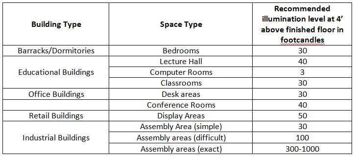
To put this all into context, a dome skylight 24” in diameter, elevated a foot above a 30’ high roof on a 20’ x 20’ grid on an open building in El Paso, Texas, achieves about 25 footcandles at a level 4’ above the floor at noon on March 21st (typical spring equinox). Compare this versus the following recommended illumination levels for various tasks as recommended by The Whole Building Design Guide:
Everyone is talking about—and doing something about—sustainability. Metal roofs fit nicely into the sustainable-material equation because of their myriad traits, such as recyclability, reflectivity, longevity and durability. Another major component in the sustainability equation is renewable energy—the production of energy from renewable resources like sun and wind. A metal roof is the ideal location for solar energy production on homes, commercial buildings and recreational applications.
Why Solar Panels and Metal Roofs?
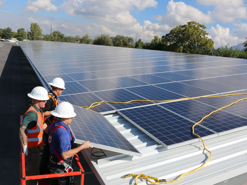
One of the key factors for long-term success of rooftop solar energy is the quality of roof under the solar panels. Roofs under photovoltaic (PV) systems should be durable and have an equivalent service life to the solar panels. However, too many traditional roof systems do not have a service life that matches, let alone exceeds, the service life of the PV panels. This is where metal roofs excel.
Solar panels will last 25 to 30 years. In fact, some of the very first PV panels from the 1960s and 1970s are still producing energy. While their efficiency might decrease over time, solar panels will make electricity for many decades. For the most cost-effective rooftop solar energy installation, the longevity of the roof should be equivalent, or greater, than the solar panels so that the roof doesn’t need replacement during the life of the solar energy system. Metal panels are the most reliable, long-term roofing system for solar energy installation projects.
Built to Last
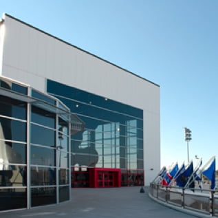
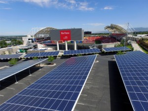
Solar Roof Panels on Real Salt Lake City Stadium
Simply put, installing solar energy on rooftops that don’t have an equivalent service life is a mistake, especially for solar projects that cover a large portion of the rooftop. The cost of decommissioning, removing, and replacing rooftop solar energy can cost 20% to 100% of the original installed cost. The cost tends to align with the percentage of rooftop covered with solar panels. Much of the cost to remove and reinstall is labor, but an older solar energy system will likely need some new components—most likely new wiring—when reinstalled, also adding to the cost.
Rooftop solar installations continue to grow year over year. And with the extension of the federal investment tax credit for five years, expect more solar energy installations on roofs. Pair solar energy with a metal roof, and you’ve hit a sustainable “home run.”
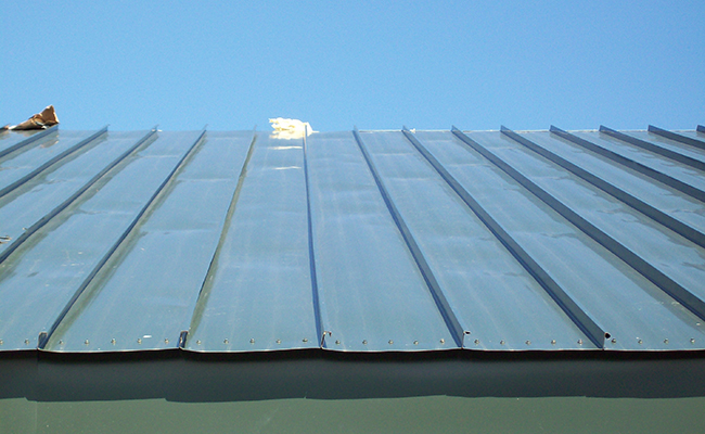
Oil canning is defined as the visible waviness in the flat portion of a metal panel. Oil canning is a visual issue, not a weatherproofing or performance issue. However, building owners will complain about waviness in metal panels on roofs, walls, and perimeter edge metal. Edge metal and metal wall panels are more of a concern than low-slope metal panels because edge metal and wall panels are visible from the ground. Steep-slope metal panels and shingles are also visible, so awareness of potential oil canning is important.
What Causes Oil Canning?
Oil canning can happen when unwanted stresses are introduced at fasteners, clips, and over purlins and uneven substrates. Over-driven fasteners, clips that are slightly misaligned relative to the clip/seam interface, and too much insulation between the purlins and panels can introduce these unwanted stresses. A misaligned panel or edge metal clip, certainly after the seam or drip edge is crimped tight, will add stresses to metal panels and edge metal
Tips to Help Prevent Oil Canning
Place clips correctly: Setting clips in the proper location for edge metal and metal panels (roof and wall) is critical. The clip needs to fit into a panel seam without forcing the vertical seam out of plane. The clip needs to be aligned correctly and sized appropriately to not compress the vertical portion of the seam. Clips that secure edge metal need to be positioned correctly so that crimping the drip edge won’t twist or bend the edge metal.
Although not highly visible, low-slope structural panels can oil-can at clip locations and where insulation is draped over purlins. Compressed insulation at purlins can “push back,” adding stress to the panel and resulting in oil canning.
Consider the roof color: Sometimes oil canning is inevitable. The color of the metal or coating won’t really make a visual difference, but darker colors panels will heat up more in direct sunlight. This may make oil canning worse in some cases. However, striations and small ribs (which also add strength) may help prevent or hide oil canning.
Choose a thick metal: Metal thickness matters, so specify metal that’s as thick as possible to avoid oil canning. Thicker metals are stiffer, so they may resist deformation due to unwanted stresses. This reduces the chance of oil canning in edge metal and wall panels, which are most commonly smooth-surfaced.
For more information on oil canning and its causes, see the Metal Construction Association’s white paper on the subject, which can be found at www.metalconstruction.org.
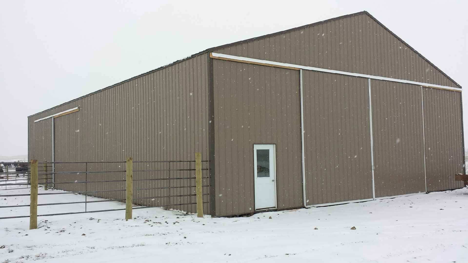
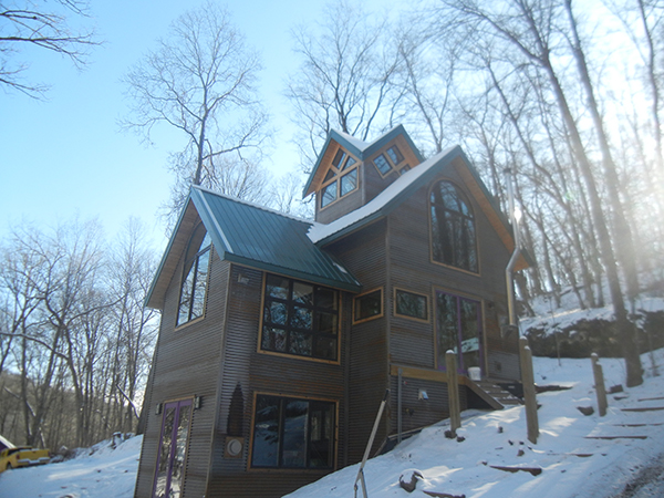
In part I of this blog, we discussed what to consider when deciding the roof material and roof slope to build with in snowy conditions. If you have decided to design a roof with metal panels, it is important to use the correct panel seams, evaluate the roof layout and consider long-term weatherproofing, and ensure your roof design fits the needs and function of the building.
Weathertight Panel Seams
For metal panel roofs less than 3:12 (i.e., low-slope roofs), the panel seams should be watertight. A watertight seam resists water intrusion, so snow on a roof should not become a leakage issue. For metal panel roofs with slope greater than 3:12, the steeper slope means liquid water (e.g., rain) drains very quickly off the roof. Because of this, many seams used for steep-slope metal panels are not watertight. Non-watertight seams can be problematic where snow stays on a roof. Architects should consider using watertight seams (e.g., double lock) and highly water-resistant underlayments in snow areas for all roof slopes.
Roof Layout
A designer should also consider the layout of the roof. Valleys collect snow. Valleys in which one roof area is significantly larger than the other (e.g., a dormer extending from a large roof area) are vulnerable to unbalanced sliding snow. A large snow slide can move across the valley and literally tear open the standing seams and displace panels.
Drifting snow can occur behind HVAC units, at perimeter walls and behind rooftop solar thermal and PV panels. Where a roof transitions from a lower low-slope roof area to an upper steep-slope roof area, snow will collect. Consider the potential snow load and entrapped moisture at these locations; the transition detail becomes critical to long-term weatherproofing. And, depending on the orientation (e.g., north facing), areas with drifted snow may not see much sunlight, so snow is more likely to stay on the roof for a longer time.
Building Function
As the roof designer, design the building and site to account for the roof’s function. Many designers turn to snow retention devices to keep snow on roofs, especially above pedestrian areas, such as entrances and outdoor seating areas, or adjacent buildings. Some of these devices rely on adhesive attachment to the panel, which means they rely on the adhesion of the paint to the metal. But physical attachment—e.g., snow fences clamped to the standing seams—is always a more confident, long-term approach than adhesive attachment when it comes to resisting shear/sliding loads. Using.multiple rows of snow fences, sometimes double in height, may be needed in areas that get large and prolonged amounts of snow (e.g., ski resorts), or where the eave to valley length is long, or where the slope is very steep. Each increases the shear loads.
Designing a Snow Retention System
Snow retention systems need to be engineered, not guesstimated! Use online models to assist with designing snow retention devices. Input your snow load, roof slope, panel width, roof length (measured horizontally), overall width of the roof area, and the manufacturer and panel type. These inputs are needed to adequately engineer a snow fence assembly. And remember, the snow loads are transferred from the fence to the panel seams, then to the panel clips and to the deck/structure. The entire load path needs to be designed to handle the snow load. Here is one model: http://www.s-5.com/calculator/index.cfm
Designing a metal roof for snow is a mix of logic, experience and engineering. We can design roofs in snow because of our everyday observations of roofs with snow on them. Stay observant; design well.
It’s February; winter storm Jonas happened last month. Snowstorms will continue to occur, and heavy snowfall can have many negative effects on roofs. What should you consider when designing a roof in snow areas, especially those with high snow amounts?
What to Consider when Building Metal Roofs
Roofs on buildings in snow areas—from a structural capacity point of view—can be designed to be any low-slope or steep-slope roof system. Roof structures can be designed and built to accommodate any anticipated snow loads. From a weather-protection point of view, snow buildup on a roof can be problematic. The extra load and the risk of leaks are not desirable; however, keeping snow on a roof is often the acceptable way to deal with it.
Roof Slope
Unquestionably, the slope of the roof matters when it comes to snow staying on or sliding off. Once a roof slope gets to be about 45 degrees (i.e., 12:12), slope becomes the overriding factor for sliding snow. The amount of snow and the roof type also matter. From a designer’s perspective, there are also a number of localized issues to consider when designing for snow on roofs.
Snow Density
The amount and density of snow also matters. More snow means more weight. More weight means a greater sliding force down (along) the slope of the roof. On slopes less than 45 degrees (e.g., 6:12 to 9:12), a low coefficient of friction (such as on smooth pan metal panels) means less resistance to sliding. Striations and embossing add a small 3D profile and improve the resistance to sliding, especially if they run transverse to the slope.
When heavy, dense snow slides it can pack a punch. Such snow sliding down a roof can shear off exhaust vents; therefore, rigid vent pipes are needed, along with a secure method of attachment. Further, installing vent pipes as high up on the slope as possible reduces the amount of potential shear load. Consider the potential load on a vent pipe that’s 5 feet from the eave with a 40-50-foot eave-to-ridge length! Reverse that and most of the load goes away.
Roof Material Type
Material type and surface color make a difference, specifically a roof’s emissivity. Metal roofing absorbs heat more quickly and radiates heat more effectively than most other roofing materials. Darker colors enhance this effect. Even with as much as 3 to 5 inches of snow, UV light passes through it; less light passes the denser the snow. (The proof: solar energy panels [photovoltaics (PV)] work when covered in some snow.) This effect only happens on sunny days, and is most effective on south-facing roof areas. If there is heat loss from the building up through the roof, the heat will help melt the snow at the roof/snow interface. This creates a potential for sliding snow.
Properly detailed and installed metal roofing is one of the most resilient, lasting, efficient and attractive kinds of roofing systems for commercial and institutional buildings. Yet there are plenty of questions about metal roofing, and building teams often find time in project meetings to address the most common, recurring topics and myths.
I call these “mythbuster meetings,” because many of the questions are fabrications – concerns arising from less savvy professionals or from competitive “selling points.” Among the most prevalent untruths:
Myth about Wind Uplift
Myth: Wind uplift affects metal roofing more than other roofing types.
Reality: While the noncontinuous nature of metal roof attachments makes them susceptible to wind uplift concerns, most roofing types are prone to similar effects. ASCE/SEI calculations for wind loading and FEMA studies of storm areas have shown that properly applied metal roofing outlasts other roof assemblies during hurricanes and tornados.
Building geometry affects how well the roof survives, regardless of roof type. Engineering determines how many insulation board fasteners are needed, and the optimal and safest distances between clips for standing seam systems at corners and perimeters, where the forces are greatest. The interlocking or “active fastening” helps metal roofing pass severe wind and uplift tests including ASTM E1592, UL 580 and UL 1897, and the Miami/Dade County codes, according to a report from Stanford University.
Myth about Heat
Myth: Metal panels get hotter and have more thermal bridging because metal conducts heat so well.
Reality: Depending upon the surface finish, metal roofing can “provide enhanced energy efficiency with its solar reflectance and infrared emittance properties […] to meet the climate requirements of the building,” according to the Stanford University paper and research highlighted by the Cool Metal Roofing Coalition.
As compared to other roofing types, metal roofing tends to be highly reflective and is available with high emissivity. Insulated metal roofing panels have foam insulation that delivers R-values up to R-8.515 per inch thickness and total roof U-factors that exceed those of many other roofing types, helping projects meet strict energy code rules.
Myth about Lightning
Myth: Metal roofs are more likely to get hit by lighting than any other roof types.
As the MCA summarizes, “Because metal roofing is an electrical conductor and a noncombustible material, the risks associated with its use and behavior during a lightning event make it the most desirable construction available.” That’s right: The best option for lightning risks.
I hope some of the above information provided insight and assurance about building with metal roofs. If you have any additional questions or concerns, submit them here to our technical experts.
One of the most important requirements for metal roof installation is ensuring that a roof stays in place when the wind blows. The core concept is that the roof’s wind resistance needs to be greater than the wind loads acting on a building’s roof. Wind resistance is most commonly determined by a physical test; wind loads are calculated.
Calculating Wind Loads
Wind loads are based on the design wind speed (which is based on the geographic location of the building), height of the roof, exposure category, roof type, enclosure classification and risk category. The height of the roof, and exposure and risk categories are factors that are used to convert design wind speed to an uplift pressure. Wind speed maps and the rules to calculate wind pressures are found in Section 1609, Wind Loads, in the 2012 or 2015 IBC. The information is based on an engineering standard written by The American Society of Civil Engineers, “ASCE 7-10, Minimum Design Loads for Buildings and Other Structures.”
Defining Exposure Risk Category
Exposure categories relate to the characteristics of the ground, such as urban and suburban areas or open terrain with some obstructions or flat areas like open water. There are 4 risk categories. Category I is low risk to humans, such as agricultural facilities. Category III includes, for example, buildings for public assembly, colleges and universities, and water treatment facilities. Category IV includes essential facilities like hospitals and police stations. Category II is everything else—most roofs are Category II. A building shall be classified as enclosed, open or partially enclosed. The enclosure classification is used to determine the internal pressure coefficients used to calculate design roof pressures.
Determining Wind Pressures
Contractors should work with a structural engineer or the metal panel manufacturer to determine the wind pressures for each roofing project. Wind pressures are determined for the field of the roof, the perimeters and the corners, where loads are largest. Only after determining the design pressures can the appropriate metal panel roof system and attachment requirements be designed.
Testing Uplift Resistance
Physical tests are the most common method to determine uplift resistance. Panel width and profile, metal type and thickness, clip type and frequency, type and number of fasteners, and the roof deck contribute to the uplift resistance of every metal panel roof system. Metal panel roof systems installed over solid substrates (with concealed clips or through-fastened) can be designed using the following test standards: FM 4471, ASTM E 1592, UL 580, or UL 1897. Metal panels installed over open framing can be designed using either ASTM E 1592 or FM 4471. Manufacturers run these tests; uplift resistance data is available for most metal panel roof systems. Installers can get this data directly from manufacturers or from web-based listing services provided by FM and UL.
Designing a Legal Metal Roof System
Wind loads and wind resistance information is necessary to verify code compliance. Get it for every project you install! Using systems that not only have been tested to the correct tests, but using systems that have uplift resistance greater than the design loads is key to a successful installation, and quite frankly, key to installing legal roof systems.
 failures at the seam openings due to any deflection of the panel. The wind clamps provide more strength, thereby dramatically improving wind uplift performance.